Motor intake sealing filtration system for hand dryer

Inactive Publication Date: 2021-11-04
SCOTT FETZER SFEG
View PDF4 Cites 0 Cited by
  • Summary
  • Abstract
  • Description
  • Claims
  • Application Information

AI Technical Summary

Benefits of technology

[0007]Both of the first and second side-mounted air intakes each include respective first and second inlet chambers that are open to the ambient air, and each are respectively, connected to first and second inlet aperture

Problems solved by technology

Thus, the ADA compliance requirement of <

Method used


Image

  • Motor intake sealing filtration system for hand dryer
  • Motor intake sealing filtration system for hand dryer
  • Motor intake sealing filtration system for hand dryer

Examples


Embodiment Construction

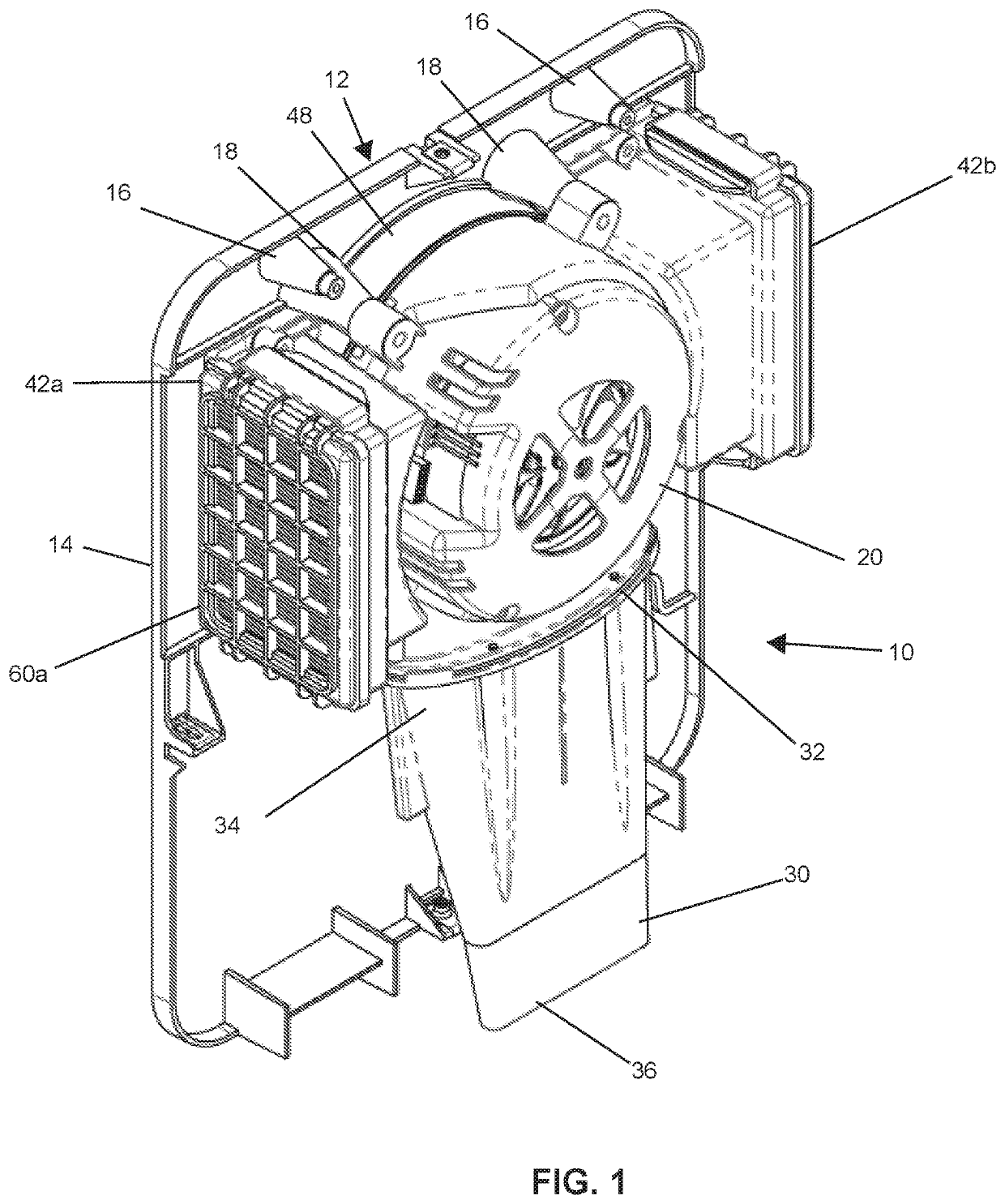
"d_n">[0020]Referring now to the drawings wherein the showings are for purposes of illustrating embodiments of the article only and not for purposes of limiting the same, and wherein like reference numerals are understood to refer to like components, a hand dryer 10 is disclosed herewith.

[0021]As shown in FIG. 1, the hand dryer 10 is depicted without an external housing (not shown) to reveal the internal components and their respective operations. It is to be appreciated that the present hand dryer 10 is retained within such a housing in order to protect the internal components from damage and to protect the user from accidentally touching electrical and moving mechanical components, as such housings are understood in the art.

[0022]As depicted in FIG. 1, the hand dryer 10 includes a mounting structure 12 having a planar backplate 14 for adjoining to a planar surface of a mounting wall upon which the hand dryer 10 is mounted. As shown in the figure, the mounting structure 12 includes...


PUM

PropertyMeasurementUnit
Heightaaaaaaaaaa
Pressureaaaaaaaaaa
Flow rateaaaaaaaaaa

Abstract

Provided in this disclosure is a hand dryer including a mounting structure having a planar surface for adjoining to a planar surface of a mounting wall upon which the hand dryer is mounted. A motor is provided for rotating a fan that generates an air flow. The motor is mounted transversely upon the mounting structure such that a plane of motor rotation is parallel to the planar surface of the mounting wall, and an axis of motor rotation is perpendicular to the mounting wall. The nozzle receives the air flow from the motor, and directs the air flow toward hands of a user. The hand dryer includes air intakes, mounted along opposite sides the motor, for receiving transverse flows of air. The air intake also includes a recessed portion, configured between the air intakes, for receiving the motor, and fluidly connecting the motor to the air intakes.

Description

I. BACKGROUNDA. Technical Field[0001]This invention pertains to the field of hand dryers that blow air onto the hands of a user to remove water after hand washing. The invention particularly pertains to hand dryers that conform with government requirements to serve the needs of special sectors of the public, such as the Americans with Disabilities Act (ADA).B. Description of Related Art[0002]Hand dryers are commonly found in public venues that blow air onto the hands of a user to remove water after hand washing. Such hand dryers include a motor that rotates an impeller or fan to direct a flow of drying air through a nozzle and onto the hands of the user.[0003]Conventional types of hand dryers, especially high-speed hand dryers, rely on a motor mounted in an axial direction for drawing air in through an intake located on the top or the side of the dryer, and directing it past the motor and out through a nozzle on the bottom. As used herein, the “axial direction” refers to a motor whi...

Claims


Application Information

Patent Timeline
IPC IPC(8): A47K10/48B01D46/00
CPCA47K10/48B01D46/0005B01D2279/00B01D2271/02B01D46/002B01D46/12B01D46/58
Inventor AMONETT, DANIEL K.QUINN, MATTHEWFINCH, ADAM
Owner SCOTT FETZER SFEG
Why Eureka
Try Eureka