Chain Cleaning Device

a cleaning device and chain technology, applied in vehicle maintenance, vehicle cleaning, transportation and packaging, etc., can solve the problems of reducing the power output of the rider, causing wear and tear of the chain, and accumulating dirt and grime on the many intricate moving parts of the chain

Active Publication Date: 2021-11-04
ROMZEK CHADWICK IRVIN
View PDF4 Cites 0 Cited by
  • Summary
  • Abstract
  • Description
  • Claims
  • Application Information

AI Technical Summary

Benefits of technology

[0007]The present invention pertains to a bicycle chain cleaning device with a track that guides a chain through a cleaning chamber. The cleaning chamber forms air flow pathways that closely surround the top and sides of the chain. The device is used with a source of pressurized air. Air discharge ports in the chamber ceiling direct a high velocity working air flow spanning the width of the chamber at the top surfaces of the chain to generate high velocity swirling air flows that progress through and around the chain. The compact nature of the cleaning chamber and the close proximity of its walls to the chain maintain the high velocity swirling air flow against the various differently oriented surfaces of the chain to remove dirt, grit and grime from the multi-surface chain, including the nooks and crannies where plates, pins and rollers come together.
[0008]An advantage of the present chain cleaning device is its ability to clean a multi-surface chain. The working air stream from the discharge ports strike the upwardly facing surfaces of chain plates, rollers and pins at a high degree of angle of about a ninety degree (90°) to effectively dislodge and remove dirt, grit and grime from these surfaces. The portion of the working air stream that deflects off the top surfaces of the chain generate turbulent or swirling air streams that redirect high velocity air flows back at the chain from a multitude of directions. The limited volume of the cleaning chamber and its pathways keeps the swirling air flows moving at a high velocity as they progress along the inside and around the sides of the chain to impact its many differently angled and oriented surfaces from many directions. The swirling air flow does not just blow by the chain surfaces, but strikes these surfaces at high degrees of angle to quickly and effectively clean dirt, grit and grime from the multi-surface chain, including the nooks and crannies and chain surfaces that do not face the discharge ports.
[0009]Another advantage of the present chain cleaning device is the U-shaped pathway formed by the cleaning chamber around three side of the perimeter of the chain. This horseshoe shaped or U-shaped pathway allows a constant flow of the high velocity air streams from the discharge ports when either the open or closed profile of the chain is aligned under the ports. The chamber ceiling is recessed from the top surface of the chain to create a pathway above the chain spanning from the front chamber wall to the rear chamber wall. The ceiling path flows into and merges with both the front and rear chamber pathways extending along the outside side surfaces of the chain. This horseshoe shaped pathway allows the high velocity working air flow from the discharge ports to flow into the side pathways when the chain restricts or blocks the flow of air through the inside of the chain. When a chain link is aligned in the chamber so that the discharge ports are directly over the side plates and the open interior is between them, much of the air flow progresses through the inside of the chain. When the ends of two adjacent chain links are aligned in the chamber so that the discharge ports are over the chain plates, rollers and pins, less air flow passes through the inside of the chain, and more air flow passes through the side pathways so that the volumetric air flow through the discharge ports remains relatively constant. The increased amount of or surge in high velocity working and turbulent air flow through the side pathways improve the ability of the device to efficiently clean the outside surfaces of the chain.

Problems solved by technology

This real world environment is kicked up by the wheels onto the oiled or greased chain, causing dirt, grit and grime to accumulate on the many intricate moving parts of the chain.
The dirt, grit and grime cause friction, results in wear and tear on the chain and reduces rider power output.
Unfortunately, these devices have proven less than ideal.
While they clean much of the dirt and grime, these devices do not fully engage the entire chain and leave smaller particles that can inhibit the optimal performance of the chain and reduce its useful life.
Using more aggressive or harsh solvents lead to alternate problems, as they can actually seep into and damage the internal lubrication of the chain links.
Yet, harsh solvents are toxic to people, animals and the environment.
Blowing toxic solvents around in a work area is a health hazard, particularly when the work area is confined.
The Feldstein device does not provide structure around the chain or produce air forces acting on the chain to clean a multi-surface chain.
Spattering the pool of solvent would defeat the purpose of drying the chain.
Similarly, spraying the liquid solvent on the chain with force will push solvent into spaces between the rollers, bushings and connecting pins, which will lead to increased wear and tear on the chain.
Using compressed air to blow dirt and debris from a chain is also well known, but there are several problems with this manner of cleaning.
Maintaining the nozzle in alignment with and close to the chain is awkward.
These components have surfaces that face a variety of directions, and their joints form a variety of nooks and crannies in which the grit and grime gets lodged, which make cleaning the chain more difficult.
This is monotonous and time consuming, and invariably leads to missing many surfaces.

Method used


Image

  • Chain Cleaning Device
  • Chain Cleaning Device
  • Chain Cleaning Device

Examples


Embodiment Construction

[0041]While this invention is susceptible of embodiments in many different forms, the drawings show and the specification describes in detail a preferred embodiment of the invention. It should be understood that the drawings and specification are to be considered an exemplification of the principles of the invention. They are not intended to limit the broad aspects of the invention to the embodiment illustrated.

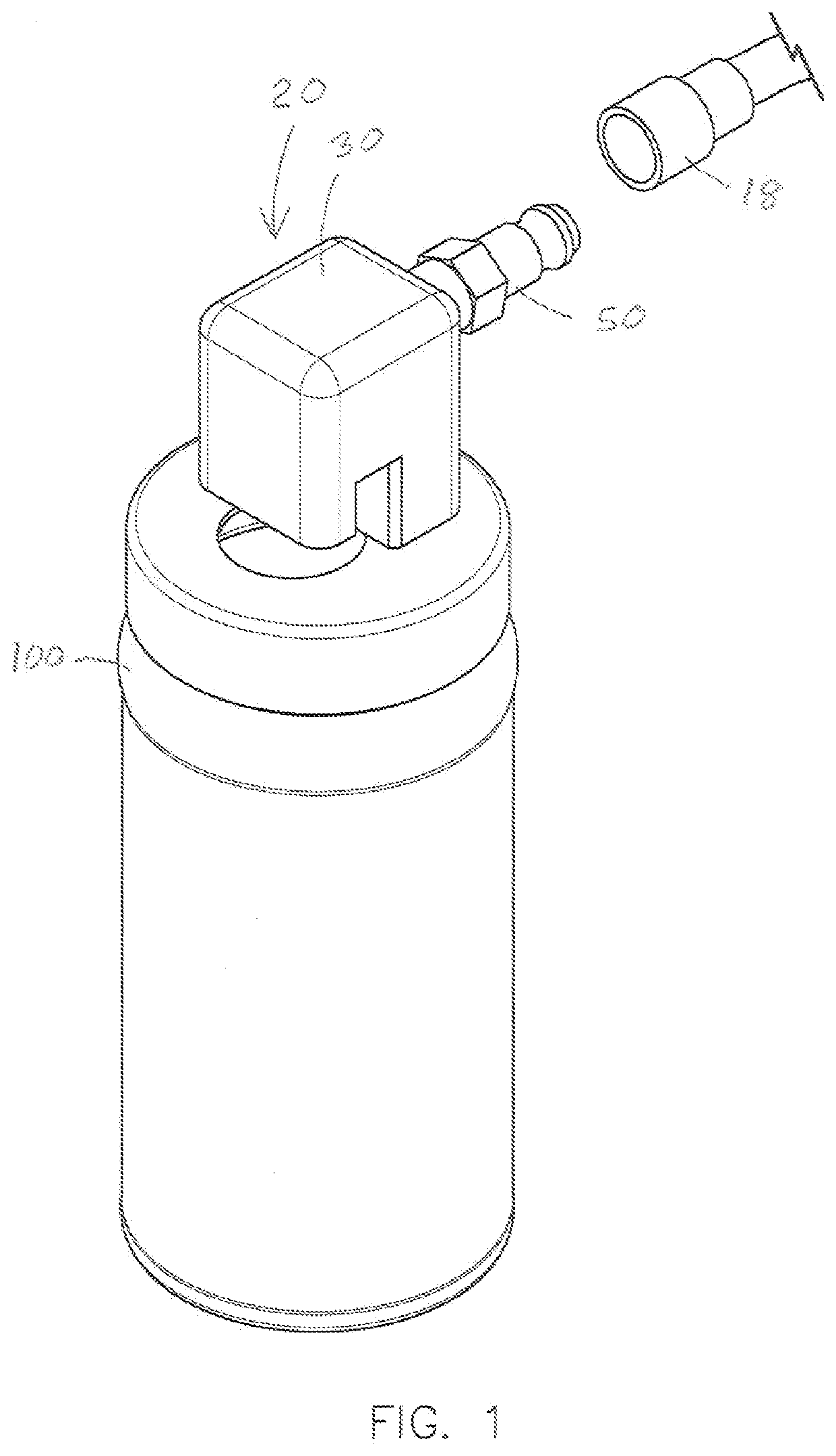
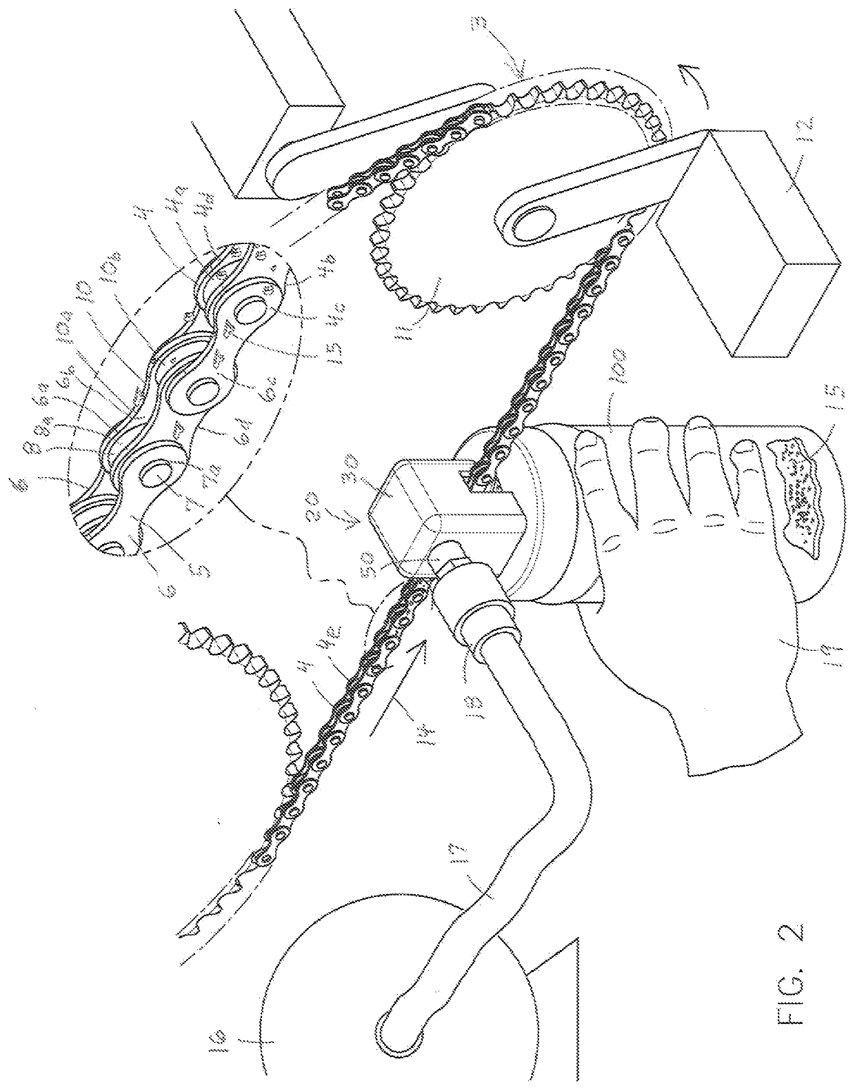
[0042]Bicycles 3 have a drive chain 4 with a top and bottom or crosswise chain surfaces 4a and 4b, opposed lateral side chain surfaces 4c and a chain perimeter 4d as best shown in FIG. 2. The looped chain 4 is formed by a series of interconnected like-shaped links 5. Each link 5 includes two thin, parallel, side plates 6 joined at their ends by perpendicular connecting pins 7 and spaced apart by rollers 8. Bushings (not shown) are between the co-linear pins 7 and rollers 8. The side plates 6 are free to rotate about the pins 7 to give the chain 4 a great amount of flexibility...


PUM


Abstract

The present invention is a chain cleaning device with a track that guides a chain through a cleaning chamber. The cleaning chamber forms air flow pathways along the sides of the chain. Discharge ports in the chamber ceiling direct a high velocity working air flow spanning the width of the chamber at the upper surfaces of the chain to generate high velocity swirling air flows that progress through the interior openings of the chain and through the pathways along the outer sides of the chain. The compact nature of the cleaning chamber and the close proximity of its walls to the chain maintain the high velocity working and swirling air flows against the various differently oriented surfaces of the chain to remove dirt, grease, grit and grime from the multi-surface chain, including the nooks and crannies where chain plates, pins and rollers come together.

Description

TECHNICAL FIELD OF THE INVENTION[0001]This invention relates to a chain cleaning device with a track to align a moving chain with a compact cleaning compartment with lateral air flow pathways along the outer side surfaces of the chain and directing a high velocity air flow across the top surface of the chain to generate a confined high velocity working and swirling air flows through and around the chain to remove dirt, grease, grit and grime from the various differently oriented surfaces of the chain.BACKGROUND OF THE INVENTION[0002]Bicycles transfer rider power to wheel power via foot pedals, sprockets and a drive chain. These drive chains perform best when clean and properly lubricated. The cleaner the chain, the more effective the lubricant and the more efficiently the chain transfers power. Efficient power output is desirable for recreational bicycling and critical for racing. Yet, recreational bicycling and bicycle racing take place over a wide variety of terrains, such as dirt...

Claims


Application Information

Patent Timeline
Patent Type & Authority Applications(United States)
IPC IPC(8): B60S3/04B08B5/02B62J50/16
CPCB60S3/041B60S3/044B62J50/16B08B5/023
Inventor ROMZEK, CHADWICK IRVIN
Owner ROMZEK CHADWICK IRVIN
Why Eureka
Try Eureka