
Projection unit for low beam light of vehicle and vehicle lamp using same

a projection unit and low beam light technology, applied in the field of vehicle lamps, can solve the problems of large accumulative errors, large complex assembly relationship, etc., and achieve the effect of reducing the size and space of the vehicle lamp, reducing the fluctuation in product performance, and reducing the assembly of the uni

Inactive Publication Date: 2021-11-18
HASCO VISION TECHNOLOGY CO LTD
View PDF0 Cites 2 Cited by
  • Summary
  • Abstract
  • Description
  • Claims
  • Application Information

AI Technical Summary

Benefits of technology

The invention provides a novel projection unit for a low beam light of a vehicle and a vehicle lamp using the same. The unit can realize the functions of vehicle lamps with the requirement for a bright and dark cut-off line, such as low beam lights and fog lamps, as well as the functions of vehicle lamps without the requirement for a bright and dark cut-off line, such as high beams, daytime running lamps, parking lamps, brake lamps, backup lamps and steering lamps. The specific structure, connection and arrangement of the light source, reflection plate, and optical lens of the projection unit can replace a reflector and a light shield which are indispensable in the prior art, reducing the size and space of the vehicle lamp and improving product performance. A secondary light distribution member is additionally arranged to improve the luminous efficacy of the secondary illumination light shape. The vehicle lamp has the functions of low beam lights and fog lamps, and a flat design is realized. The manufacturing errors of parts and the assembly of units are reduced.

Problems solved by technology

However, the bifocal reflector like an ellipsoidal surface has a large depth, thus occupying a large space and being disadvantageous for a flat design of a vehicle lamp, which has great advantages and is becoming a development trend.
In addition, the existing projective vehicle lamp illumination system has too many parts, so that the assembly relationship of the parts is complicated; and the manufacturing errors of parts and the assembly of units lead to a great fluctuation in product performance.
For example, the complaint of customers about inconsistent brightness of left and right lamps, and the manufacturing cost is relatively high.
In addition, the existing projective vehicle lamp illumination system is composed of too many parts (for example, the existing projective vehicle lamp illumination system is essentially provided with the reflector and the light shield plate), thus having the defects of a large weight, a complicated assembly relationship and large accumulative errors.
The bifocal reflector like an ellipsoidal surface has a large depth, thus occupying a large space and being disadvantageous for a flat design of a vehicle lamp;
The existing projective vehicle lamp illumination system has too many parts, so that the assembly relationship of the parts is complicated; and the manufacturing errors of parts and the assembly of units lead to a large weight of the illumination system, a complicated assembly relation, large accumulative errors and a great fluctuation in product performance.

Method used


Image

  • Projection unit for low beam light of vehicle and vehicle lamp using same
  • Projection unit for low beam light of vehicle and vehicle lamp using same
  • Projection unit for low beam light of vehicle and vehicle lamp using same

Examples


embodiment 1

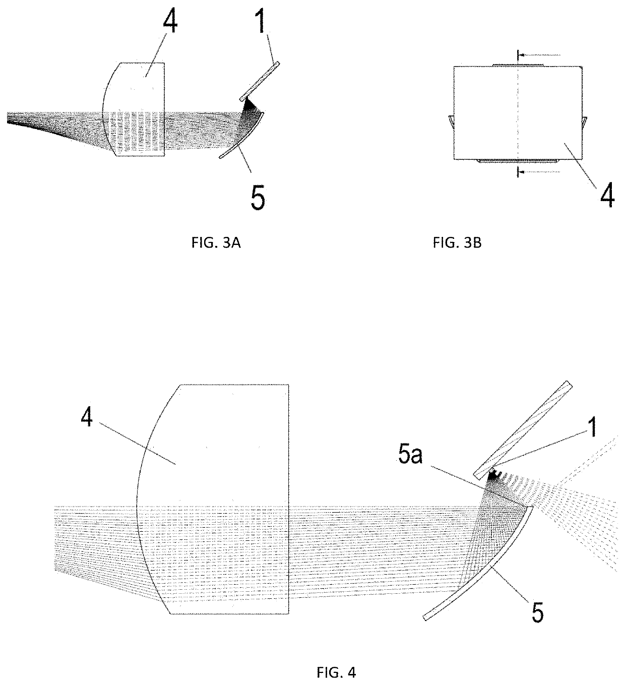
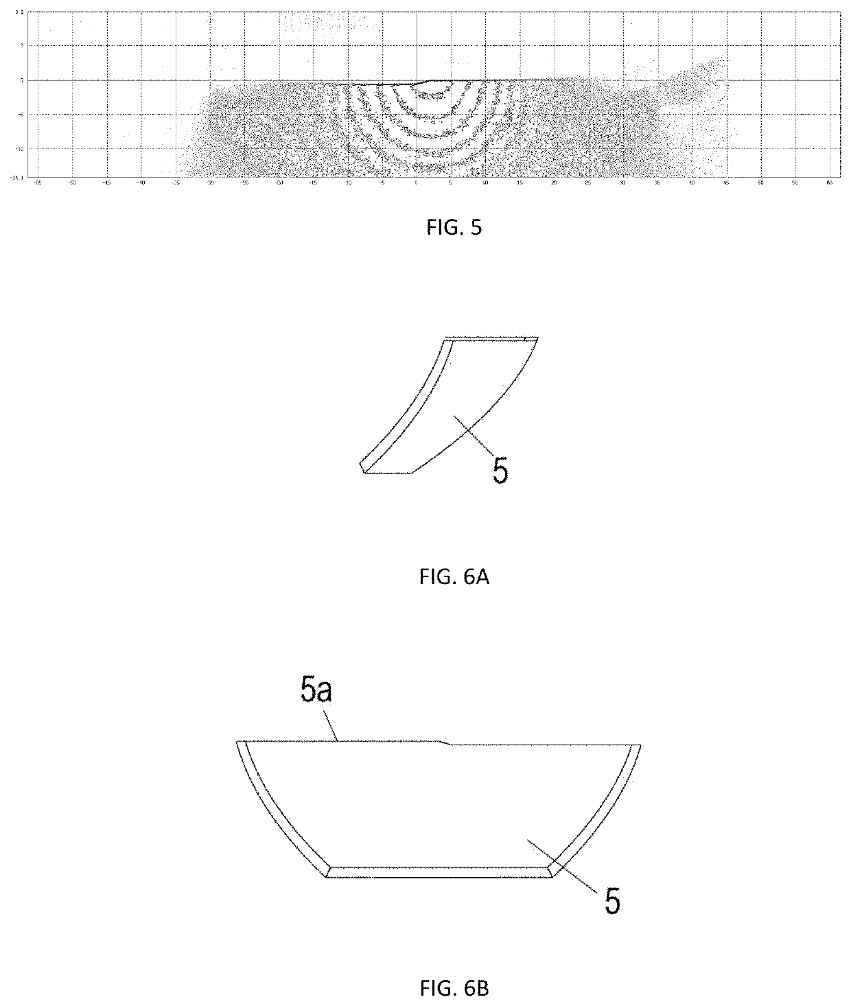
[0068]A projection unit for a low beam light of a vehicle comprises a light source and an optical lens, and is provided with a reflection plate, wherein an upper boundary of the reflection plate is provided with a boundary corresponding to the shape of a bright and dark cut-off line required by an illumination light shape of a vehicle lamp system to replace a light shield plate and a boundary of the light shield plate, and the reflection boundary of the reflection plate is arranged near a focus of the optical lens. The light source is an LED surface light source. The light source illuminates the reflection plate, and light rays reflected by the reflection plate form an initial illumination light shape and then illuminate a road surface through the optical lens to form a final illumination light shape with a bright and dark cut-off line.

[0069]An optical axis of the light source of the projection unit deviates from the normal of the reflection plate by 45°, the reflection plate is arr...

embodiment 2

[0072]This embodiment is identical with Embodiment 1 except in the following aspect:

[0073]A secondary light distribution member is additionally arranged between the light source and the reflection plate. The secondary light distribution member is a convex lens or a reflector, and is used for converging the light rays or changing the light energy distribution to improve the luminous efficacy.

embodiment 3

[0074]This embodiment is identical with Embodiment 1 except in the following aspect:

[0075]The reflection boundary of the reflection plate is arranged 0-5 mm away from the focus of the lens.


PUM


Abstract

Disclosed are a projection unit for a low beam light of a vehicle, and a vehicle lamp. The projection unit is composed of a light source, a reflection plate and an optical lens. Wherein the reflection plate is provided with a reflection boundary corresponding to the shape of a bright and dark cut-off line required by an illumination light shape of a vehicle lamp system, and the reflection plate is a plane reflector, a curved reflector, or a reflector formed by connecting multiple curved surfaces. The reflection boundary is arranged near a focus of the optical lens, the light source illuminates the reflection plate, and light rays reflected by the reflection plate form an initial illumination light shape.

Description

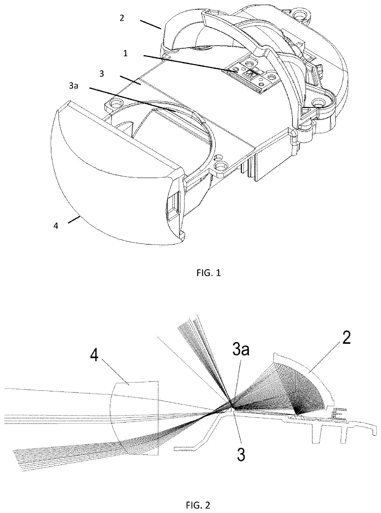
BACKGROUND OF THE INVENTION1. Technical Field[0001]The invention relates to the technical field of vehicle lamps, and particularly relates to a projection unit for a low beam light (dipped headlight) of a vehicle and a vehicle lamp using the same. The projection unit for a low beam light of a vehicle and the vehicle lamp using the same can realize the functions of vehicle lamps with the requirement for a (bright and dark) cut-off line such as low beam light and fog lamps, and can also realize the functions of vehicle lamps without the requirement for a cut-off line.2. Description of Related Art[0002]An existing projective vehicle lamp illumination system is typically composed of a light source 1, a reflector 2, a light shield plate 3 and an optical lens 4.[0003]As shown in FIG. 1, the reflector 2 is generally a reflection surface like a parabolic surface and has a near focus and a far focus, the light source 1 is arranged at the near focus, Lambertian-like divergent light emitted by...

Claims


Application Information

Patent Timeline
Patent Type & Authority Applications(United States)
IPC IPC(8): F21S41/148F21S41/32
CPCF21S41/148F21W2102/135F21S41/32F21S41/25F21S41/147
Inventor ZHANG, JIEDONG, SHIKUNMENG, FANLI, FEIQUANCHEN, JIAYUAN
Owner HASCO VISION TECHNOLOGY CO LTD
Learn More