
Anaesthetic vaporizer filler

a technology of anaesthetic vaporizer and filler, which is applied in the field of anaesthetic vaporizer filler, can solve the problems of large amount of liquid anaesthetic to be vented, delicate process which needed to be improved, and difficulty in filling plenum vaporizers with wrong agents

Pending Publication Date: 2021-11-25
DUNLOP COLIN +1
View PDF0 Cites 1 Cited by
  • Summary
  • Abstract
  • Description
  • Claims
  • Application Information

AI Technical Summary

Benefits of technology

The present invention is a filler for an anaesthetic vaporizer used for veterinary surgery. The filler is attached to the vaporizer and has fluid conduits and a gasket for secure attachment. The filler has a concave mounting surface that aligns with corresponding apertures in the vaporizer. The filler also has a sight window and a port unit for attaching a filler port unit. The filler has breather holes that are spaced vertically and horizontally to each other. The filler is made of brass and coated with nickel. The invention also includes a vaporizer and filler combination, where the filler is attached to the vaporizer using captive screws. The technical effects of the invention include improved anaesthetic delivery and secure attachment of the filler to the vaporizer.

Problems solved by technology

Several safety systems have been devised so that filling a plenum vaporizer with the wrong agent is extremely difficult.
Filling anaesthetic plenum vaporizers with liquid anaesthetic has been a challenge when attempting to minimize spillage of volatile liquid anaesthetic, and risk to the user.
This is due to anaesthetic inhalants being volatile liquids, with a low boiling point, and they tend to turn into vapour and increase pressure when excited by moving the bottle.
This was a delicate process which needed to be improved to address basic occupational health and safety.
In older models of vaporizer with no valve and no breather hole, this proved to be precarious and could cause a large amount of liquid anaesthetic to be vented from the filler when the bottle conduit is withdrawn from the fill port as the vaporizer reservoir depressurizes.
Small amounts of anaesthetic liquid however will in most instances still depressurize over the user when removing the filler.
However due to poor design placements of this breather hole, they do not really work well, so vaporizers were still difficult to fill, and liquid could still be ejected onto the user.
Fillers have also been problematic in selecting appropriate sealing material in the valve seat, valve stem and other components.
This is because a veterinarian will typically need to fill a vaporizer at least once per week, putting high cyclic load on the valve seals.
The environment of anaesthetics in liquid form has only been suitable for only a few materials without some form of chemical reaction.
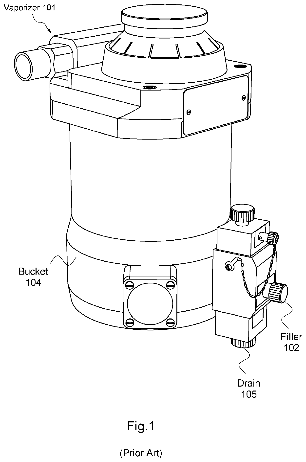
Whilst such a Tec 3 vaporizer 101 works extremely well when serviced and maintained properly, it is difficult to fill and drain without the abovementioned issues presenting themselves.
Because drain 105 extends below bucket 104, this means vaporizer 101 is not able to be placed upright on a level surface causing numerous issues during maintenance, removal and replacement, including occupational health and safety issues.
The abovementioned corrosion issues are at their worst when halothane is the anaesthetic.
Another problem with the prior art filler 102, is that it has a square / rectangular edge configuration, and this with the various protruding components thereon, makes it more likely to have gas conduits and the like to catch or snag thereon when in use, adding a further complication to occupational health and safety issues.
As such the prior art vaporizers have posed serious leakage and spillage problems associated with filling them with liquid anaesthetic. mainly due to the design and attachment of the filler.
Those fillers attached from inside the reservoir have additional occupational health and safety issues, as the filler can only be removed by disassembly of the vaporizer, which requires additional safety precautions, such as disassembly in a fume hood, adding considerably time and expense to service.
Furthermore, the filler gauges (sight glass level indicators) in prior art vaporizers have been quite small, making them difficult to see during filling, and related to the limited capacity of anaesthetic that can be introduced into the vaporizer.
Most of the prior art vaporizers made for veterinary use in recent times have used fillers that have requiring expensive six-axis CNC machines for manufacture, with considerable wastage of materials and significant plugging.

Method used


Image

  • Anaesthetic vaporizer filler
  • Anaesthetic vaporizer filler
  • Anaesthetic vaporizer filler

Examples


Embodiment Construction

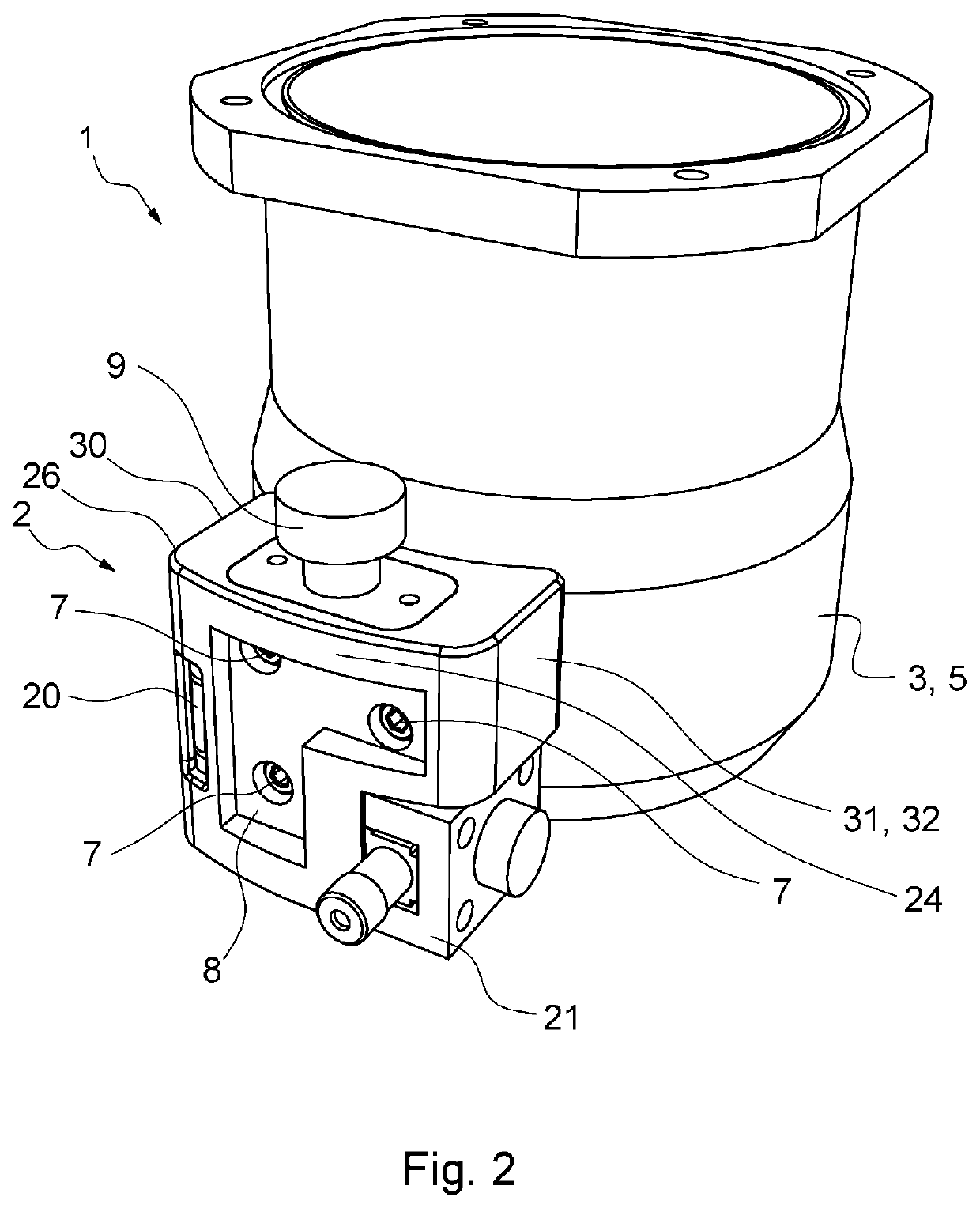
[0040]FIGS. 2 to 7 depict a first embodiment of a vaporizer 1 and a filler 2 attached thereto. Vaporizer 1 is preferably an anaesthetic vaporizer used with anaesthetic machine for veterinary patients.

[0041]External bucket 3 and the internal reservoir (not shown) disposed therein of vaporizer 1 are made of aluminium that is nickel coated by electroless process for heavy corrosion resistance, and then chrome finished for aesthetic purposes. The nickel coating material delivered by the electroless process is impervious to modem anaesthetics such as halothane and isoflurane and penetrates deeper bores over older conventional plating.

[0042]The body of filler 2 is preferably made of solid brass and nickel coated and chrome finished for aesthetic purposes.

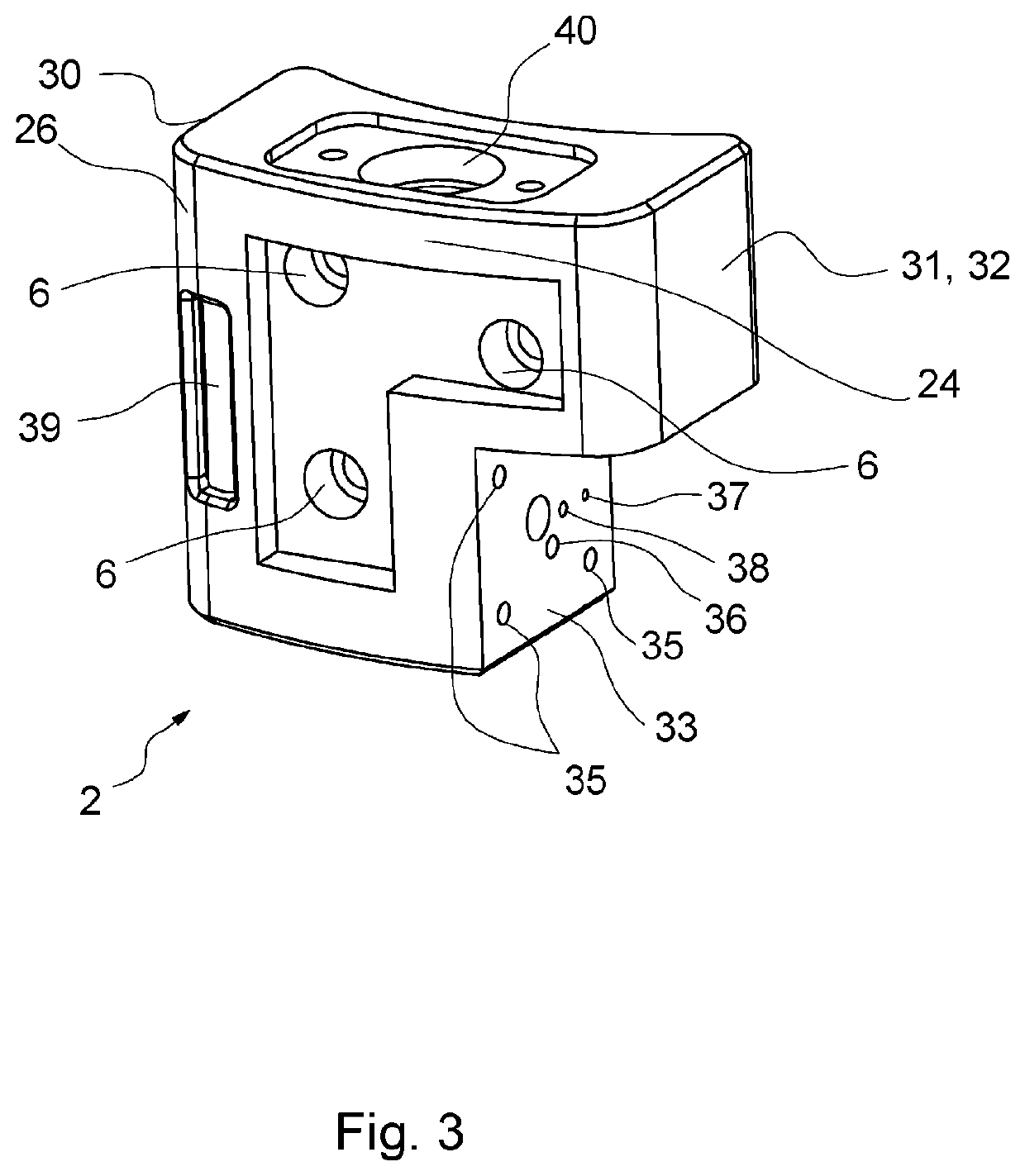
[0043]In manufacture the single block of brass used to manufacture the body of filler 2, can have the various holes / bores machined on an inexpensive three-axis CNC machine. Filler 2 is curved entirely in one plane and has a concave mounti...


PUM


Abstract

A filler for an anaesthetic vaporizer used for veterinary surgery. The filler is attached to a cylindrical bucket portion of the vaporizer. The filler is curved in shape and having a concave mounting surface that is obverse to the cylindrical bucket portion. The filler having fluid conduits therein interconnecting first apertures on the concave mounting concave surface and a filler-port unit, the first apertures on the mounting surface aligning with associated second apertures on said bucket. A gasket with a plurality of first holes aligned with first and second apertures is disposed between the bucket and the filler.

Description

TECHNICAL FIELD[0001]This invention relates to an anaesthetic vaporizer filler. In particular, the present invention is described with reference to an anaesthetic vaporizer filler for use in veterinary surgery.BACKGROUND[0002]An anaesthetic vaporizer is a device used to convert a liquid anaesthetic into a breathable form (vapour) and deliver the anaesthetic vapour in specific concentrations so that controlled doses can be administered to the patient. Many variables affect the concentration produced, to including the type and temperature of the liquid anaesthetic, the pressures in the anaesthesia system delivering the vapour, and the type and flow rate of the “carrier gases” used to produce the vapour. The carrier gas can be oxygen or a mixture of gases such as oxygen, nitrous oxide, room air, and re-breathed air.[0003]Anaesthetic vaporizers ensure effective and safe addition of inhalant anaesthetics to the fresh is gas flow exiting the common gas outlet of an anaesthetic machine. Ty...

Claims


Application Information

Patent Timeline
Patent Type & Authority Applications(United States)
IPC IPC(8): A61D7/04
CPCA61D7/04A61M16/183
Inventor DUNLOP, COLINDUNLOP, JAMES
Owner DUNLOP COLIN
Learn More