Unidirectional or Bidirectional Sand Dispensing Device

a sand and sand technology, applied in the field of 3d printers, can solve the problems of reducing the service life of the printed product, so as to achieve the effect of eliminating the leakage of sand

Active Publication Date: 2021-11-25
NINGXIA KOCEL MOLD
View PDF0 Cites 4 Cited by
  • Summary
  • Abstract
  • Description
  • Claims
  • Application Information

AI Technical Summary

Benefits of technology

[0027]As can be seen from the technical solutions described above, in the unidirectional or bidirectional sand dispensing device provided in the present disclosure, a discharge port in a staggered arrangement is designed by using the principle of angle of repose, so that a particulate material is piled up with an inclined plane in the sand discharging passage, an included angle between the inclined plane and the horizontal plane is a leakage angle, and the direction of an opening of the sand passing passage is opposite to a moving direction during the sand dispensing operation. In other words, when the sand dispensing operation is s

Problems solved by technology

Although it can be ensured that sand can be discharged and the sand surface is compacted, there is a serious phenomenon of sand leakage during the printing process, which leads to an increase in printing cost and also causes the printed product with a certain defect, and easily causes insufficient supply of sand to a sand mixing device, resulting in delaminat

Method used


Image

  • Unidirectional or Bidirectional Sand Dispensing Device
  • Unidirectional or Bidirectional Sand Dispensing Device
  • Unidirectional or Bidirectional Sand Dispensing Device

Examples


Embodiment Construction

[0037]The technical solutions of embodiments of the present disclosure will be described in further detail with reference to the drawings of the present disclosure.

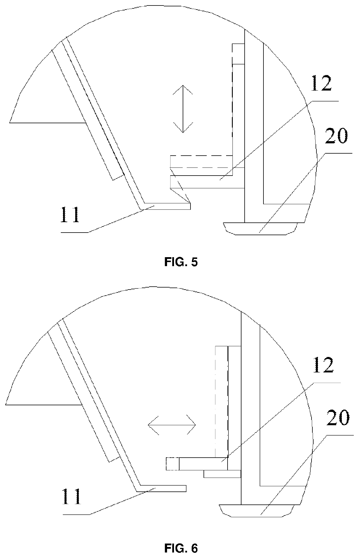
[0038]A slope of a material pile when a particulate material is naturally piled up, i.e., an included angle between the steepest plane of the material pile and a horizontal plane, is referred to as an angle of repose, wherein an angle of repose in a static state is referred to as a static repose angle, and an angle of repose of a particulate material on a sand dispensing device in a dynamic state, for example when the sand dispensing device starts to move, is referred to as a dynamic repose angle. In general, a degree of the dynamic repose angle is 70% of that of the static repose angle.

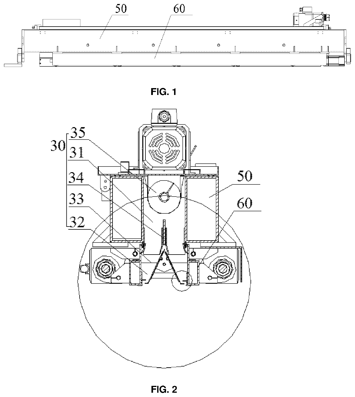
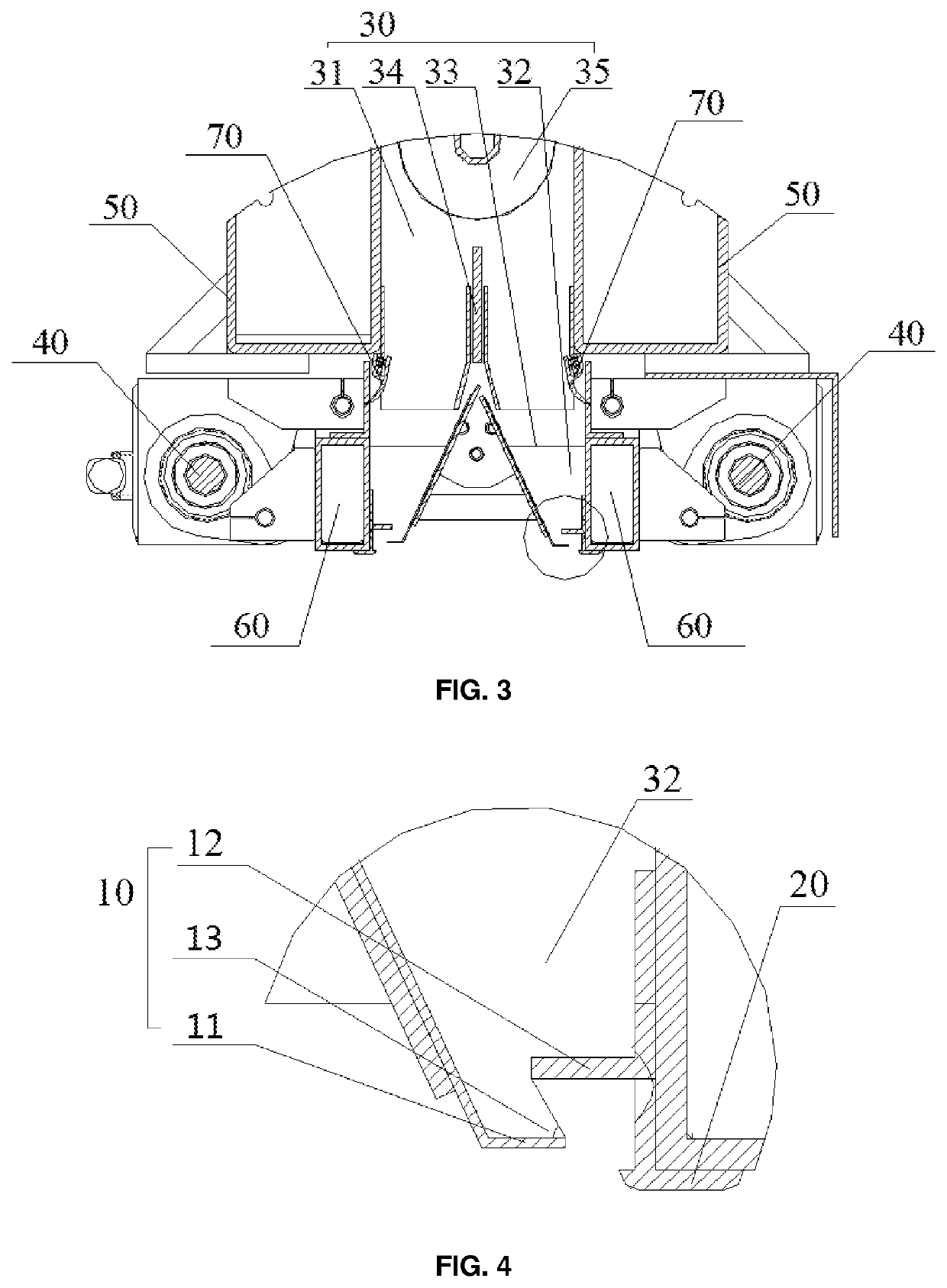
[0039]The present embodiment provides a unidirectional or bidirectional sand dispensing device. Referring to FIG. 4 in combination with FIG. 1 to FIG. 3, the unidirectional or bidirectional sand dispensing device comprises a discharge port...


PUM

PropertyMeasurementUnit
Angleaaaaaaaaaa
Angleaaaaaaaaaa
Angleaaaaaaaaaa

Abstract

A unidirectional or bidirectional sand dispensing device, including a discharge port (10), the discharge port includes a lower plate (11) and an upper plate (12), the upper plate is provided above the lower plate, an included angle between a horizontal plane and a straight line where an endpoint of a free end of the upper plate and an endpoint of a free end of the lower plate are located is a leakage angle (13), that is to say, a particulate material forms an inclined plane between the upper plate and the lower plate, and an included angle between the inclined plane and the horizontal plane is the leakage angle, which can be adjusted by changing relative positions of the upper plate and the lower plate. The direction of an opening of the sand passing passage is opposite to a moving direction during the sand dispensing operation. When the sand dispensing operation is stopped, the leakage angle is less than or equal to the static repose angle of the particulate material, and is greater than or equal to zero, which ensures that the particulate material will not slide down, and the phenomenon of sand leakage is eliminated. When the sand dispensing operation is being carried out, the leakage angle is greater than or equal to the dynamic repose angle of the particulate material, which ensures that the particulate material will slide down along the inclined plane and that the sand is dispensed relatively uniformly.

Description

CROSS-REFERENCE TO RELATED APPLICATIONS[0001]The present disclosure claims priority of Chinese Patent Application No. 201810812221.7, filed with the Chinese Patent Office on Jul. 23, 2018, entitled “Unidirectional or Bidirectional Sand Dispensing Device”, the contents of which are incorporated herein by reference in their entirety.TECHNICAL FIELD[0002]The present disclosure relates to the field of 3D printers, and in particular to a unidirectional or bidirectional sand dispensing (spreading) device.BACKGROUND ART[0003]At present, a sand dispensing device used in a sand mold three-dimensional (3D) printing apparatus has a discharge port opened in a straight manner. Although it can be ensured that sand can be discharged and the sand surface is compacted, there is a serious phenomenon of sand leakage during the printing process, which leads to an increase in printing cost and also causes the printed product with a certain defect, and easily causes insufficient supply of sand to a sand ...

Claims


Application Information

Patent Timeline
IPC IPC(8): B22C5/14B33Y30/00B33Y80/00
CPCB22C5/14B22C9/02B33Y80/00B33Y30/00B22F12/52B22F12/55B22F2999/00Y02P10/25B22F2202/01
Inventor PENG, FANYANG, BAOHE, JIEJUNXU, YUNLONGWANG, YANTAO
Owner NINGXIA KOCEL MOLD
Why Eureka
Try Eureka