Enhanced refrigeration purge system

Pending Publication Date: 2021-11-25
CARRIER CORP
View PDF2 Cites 0 Cited by
  • Summary
  • Abstract
  • Description
  • Claims
  • Application Information

AI Technical Summary

Benefits of technology

The patent describes a method for purging contaminants from a refrigerant of a heat pump via a purge system. The method involves monitoring various parameters of the purge system and the heat pump, and actively controlling operational parameters of the purge system based on the monitoring results. This allows for efficient purging of the refrigerant from the heat pump. The technical effect of the patent is to provide a more effective and efficient method for purging contaminants from a heat pump's refrigerant.

Problems solved by technology

As a result, leaks in the chiller system may draw air into the system, contaminating the refrigerant.
This contamination degrades the performance of the chiller system.
Existing purge units are complicated and lose refrigerant in the process of removing contamination.

Method used


Image

  • Enhanced refrigeration purge system
  • Enhanced refrigeration purge system
  • Enhanced refrigeration purge system

Examples


Embodiment Construction

[0038]A detailed description of one or more embodiments of the disclosed apparatus and method are presented herein by way of exemplification and not limitation with reference to the Figures.

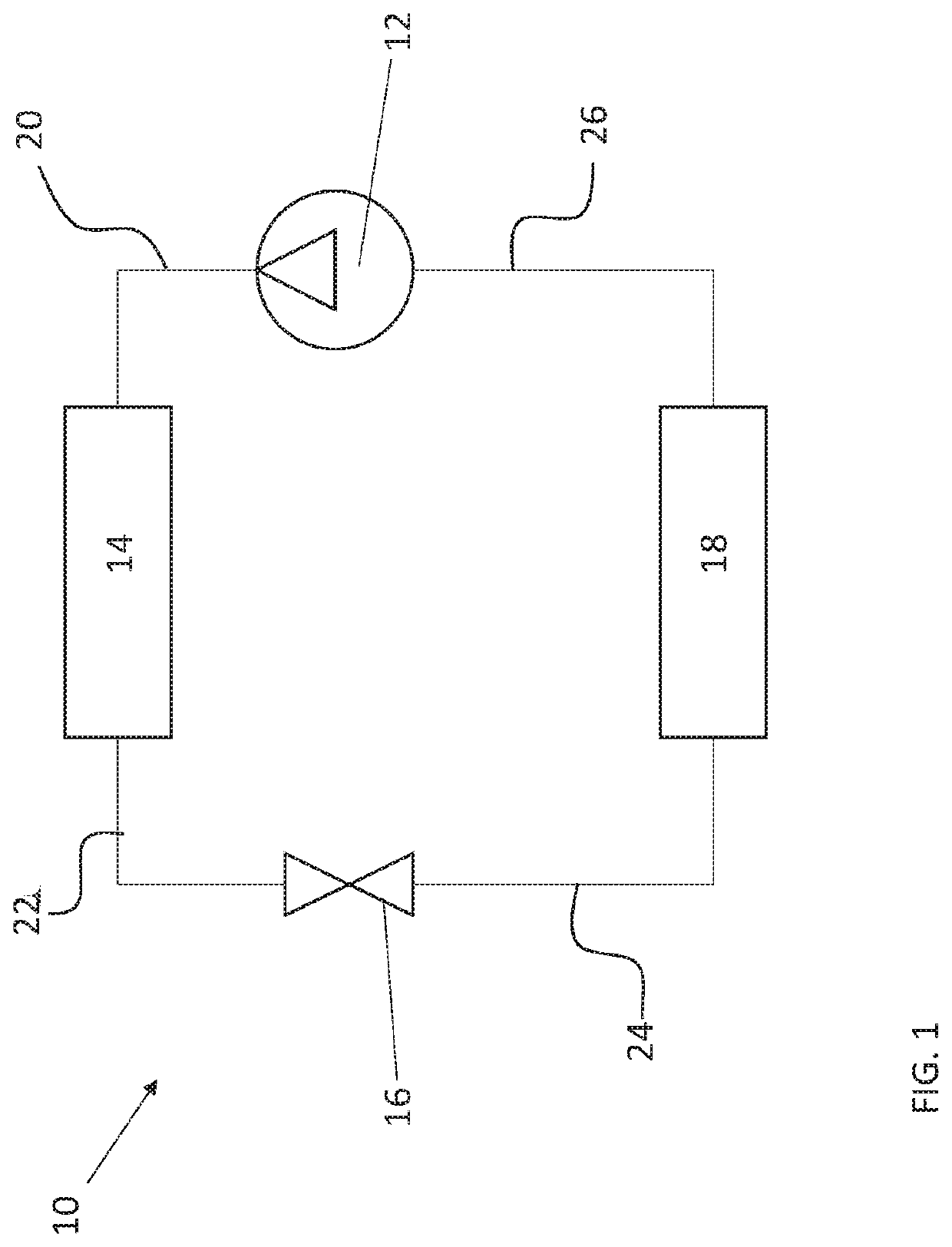
[0039]Referring now to FIG. 1, an example of a heat pump 10 is illustrated. As used herein, the term heat pump is intended to include any system capable of heating and / or cooling, such as a vapor compression system, a sorption system, a geothermal system, a waste heat recovery system, a heat based cooling system, and a heating system. As shown, heat pump 10 includes a compressor 12, a condenser 14, an expansion valve 16, and an evaporator 18. The compressor 12 pressurizes heat transfer fluid in its gaseous state, which both heats the fluid and provides pressure to circulate it through the system. In some embodiments, the heat transfer fluid, or refrigerant, includes an organic compound. For example, in some embodiments, the refrigerant comprises at least one of a hydrocarbon, substituted hydrocar...


PUM


Abstract

A method of purging contaminants from a refrigerant of a heat pump via a purge system includes generating a driving force across a separator, providing refrigerant including contaminants to the separator, separating the contaminants from the refrigerant within the separator, monitoring one or more parameters of the purge system and the heat pump, and actively controlling an operational parameter of the purge system in response to monitoring one or more parameters of the purge system and the heat pump.

Description

CROSS REFERENCE TO RELATED APPLICATIONS[0001]This application claims the benefit of U.S. Application No. 62 / 774,725, filed on Dec. 3, 2018, which is incorporated herein by reference in its entirety.BACKGROUND[0002]Embodiments of the present disclosure relate generally to chiller systems used in air conditioning systems, and more particularly to a purge system for removing contaminants from a refrigeration system.[0003]Chiller systems such as those utilizing centrifugal compressors may include sections that operate below atmospheric pressure. As a result, leaks in the chiller system may draw air into the system, contaminating the refrigerant. This contamination degrades the performance of the chiller system. To address this problem, existing low pressure chillers include a purge unit to remove contamination. Existing purge units typically use a vapor compression cycle to separate contaminant gas from the refrigerant. Existing purge units are complicated and lose refrigerant in the pr...

Claims


Application Information

Patent Timeline
IPC IPC(8): F25B43/04F25B49/02B01D53/047
CPCF25B43/043F25B49/02B01D53/047F25B2600/2505F25B2700/195B01D2257/104F25B2700/1931B01D53/22B01D2257/504B01D2257/106B01D2257/102B01D2257/80Y02C20/40
Inventor RANJAN, RAJIVFENG, YINSHANVERMA, PARMESHSTARK, MICHAEL A.
Owner CARRIER CORP
Why Eureka
Try Eureka