Logarithm calculation method and logarithm calculation circuit

a technology of logarithm and calculation method, applied in the field of logarithm calculation method, can solve the problems of increasing the complexity and cost of circuit design, and achieve the effect of greatly simplifying the circuit design

Pending Publication Date: 2021-11-25
REALTEK SEMICON CORP
View PDF2 Cites 0 Cited by
  • Summary
  • Abstract
  • Description
  • Claims
  • Application Information

AI Technical Summary

Benefits of technology

[0003]It is therefore an objective of the present invention to provide a logarithm calculation method and related circuits, which only need two addition

Problems solved by technology

However, the above method needs to store a large parameter table, and also need to use many multipliers w

Method used


Image

  • Logarithm calculation method and logarithm calculation circuit
  • Logarithm calculation method and logarithm calculation circuit

Examples


Embodiment Construction

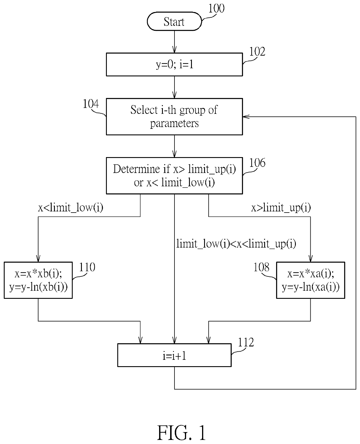
[0009]FIG. 1 is a flowchart of a logarithm calculation method according to one embodiment of the present invention. As shown in FIG. 1, in Step 100, the flow starts, and an initial input value x is prepared to perform a logarithm operation to obtain an output value y, that is, y=ln(x). In Step 102, the output value y is set to 0, and a parameter i is set to 1 (that is, the first iteration operation is performed), and the initial input value x is converted into a floating-point number, that is the initial input value x is converted to x=m*2{circumflex over ( )}n, where n is a positive integer and m is a value between 0.5 and 1. In one embodiment, m can be a 16-bit digital value, and n can be a 6-bit digital value. In step 104, the i-th group of parameters are selected, where the i-th group of parameters includes xa(i), xb(i), limit_up(i), limit_low(i), at this time, since i is equal to 1, the xa(1), xb(1), limit_up(1), limit_low(1) in the first group of parameters are (1 / 2), (3 / 2), (...


PUM


Abstract

The present invention provides a logarithm calculation method, wherein the logarithm calculation method includes the steps of: (a) selecting a first parameter, a second parameter, a third parameter and a fourth parameter corresponding to an i-th iteration operation; (b) determining whether an input value is greater than the third parameter or smaller than the fourth parameter (c) if the input value is greater than the third parameter, updating the input value by multiplying the first parameter, and updating an output value by subtracting a logarithmic value of the first parameter; if the input value is less than the fourth parameter, updating the input value by multiplying the second parameter, and updating the output value by subtracting a logarithmic value of the second parameter (d) adding one to ‘i’ and return to step (a); (e) when ‘i’ is equal to a predetermined value, outputting the current output value.

Description

BACKGROUND OF THE INVENTION1. Field of the Invention[0001]The present invention relates to a logarithm calculation method.2. Description of the Prior Art[0002]In a conventional logarithm calculation circuit, a coordinate rotation digital computer (CORDIC) is usually used to achieve logarithm calculations. However, the above method needs to store a large parameter table, and also need to use many multipliers with complicated circuit designs. Therefore, it will increase the complexity and cost of the circuit design.SUMMARY OF THE INVENTION[0003]It is therefore an objective of the present invention to provide a logarithm calculation method and related circuits, which only need two addition operations and one shift operation in each iteration operation, so the circuit design can be greatly simplified to solve the problems in the prior art.[0004]According to one embodiment of the present invention, a logarithm calculation method for performing a logarithm operation on an initial input va...

Claims


Application Information

Patent Timeline
IPC IPC(8): G06F7/483G06F7/485G06F7/487G06F5/01
CPCG06F7/4833G06F5/01G06F7/4876G06F7/485G06F7/556G06F2101/10
Inventor ZHAO, BOYAQIU, DONGTANG, MINGZHEWU, YAN
Owner REALTEK SEMICON CORP
Why Eureka
Try Eureka