Vehicle wheel having adjustable insert neck and method for manufacturing the same

Pending Publication Date: 2021-12-02
HYUNDAI MOTOR CO LTD +2
View PDF0 Cites 0 Cited by
  • Summary
  • Abstract
  • Description
  • Claims
  • Application Information

AI Technical Summary

Benefits of technology

The present patent is about a vehicle wheel and its manufacturing method that can form a temporary flange for machining a resonance chamber after casting a rim part and a disc configuring a vehicle wheel in a one-piece state. This allows for stable performance of processes such as flow forming and friction stir welding, reducing dimensional errors during the machining process. The wheel can also be easily adjusted to absorb the resonance sound with the target resonance frequency while reducing the weight of the wheel. The invention can also allow for easy removal of the temporary flange and adjustment of the target resonance frequency through the insertion and fastening of an insert neck to the sound-absorbing hole. Additionally, the invention can achieve reduction in the weight of the wheel and securing of the minimum length of the sound-absorbing hole even if the weight of the metal is reduced.

Problems solved by technology

However, the conventional method for manufacturing the wheel in the two-piece bonding manner has a disadvantage in that the rim part and the disc are separately manufactured and then bonded to each other by friction stir welding, thereby increasing the manufacturing cost or the like due to an increase in the number of manufacturing processes and an increase in the area required by the friction stir welding.
Accordingly, as another example of the related art, a method for performing a process of forming a resonance chamber after casting a rim and a disc configuring a vehicle wheel in one-piece state is applied, but there are disadvantages in that a dimensional error occurs during the process of machining the resonance chamber, and a target resonance frequency for absorbing the resonance sound may not be adjusted.

Method used


Image

  • Vehicle wheel having adjustable insert neck and method for manufacturing the same
  • Vehicle wheel having adjustable insert neck and method for manufacturing the same
  • Vehicle wheel having adjustable insert neck and method for manufacturing the same

Examples


Embodiment Construction

[0035]Hereinafter, exemplary embodiments of the present disclosure will be described in detail with reference to the accompanying drawings.

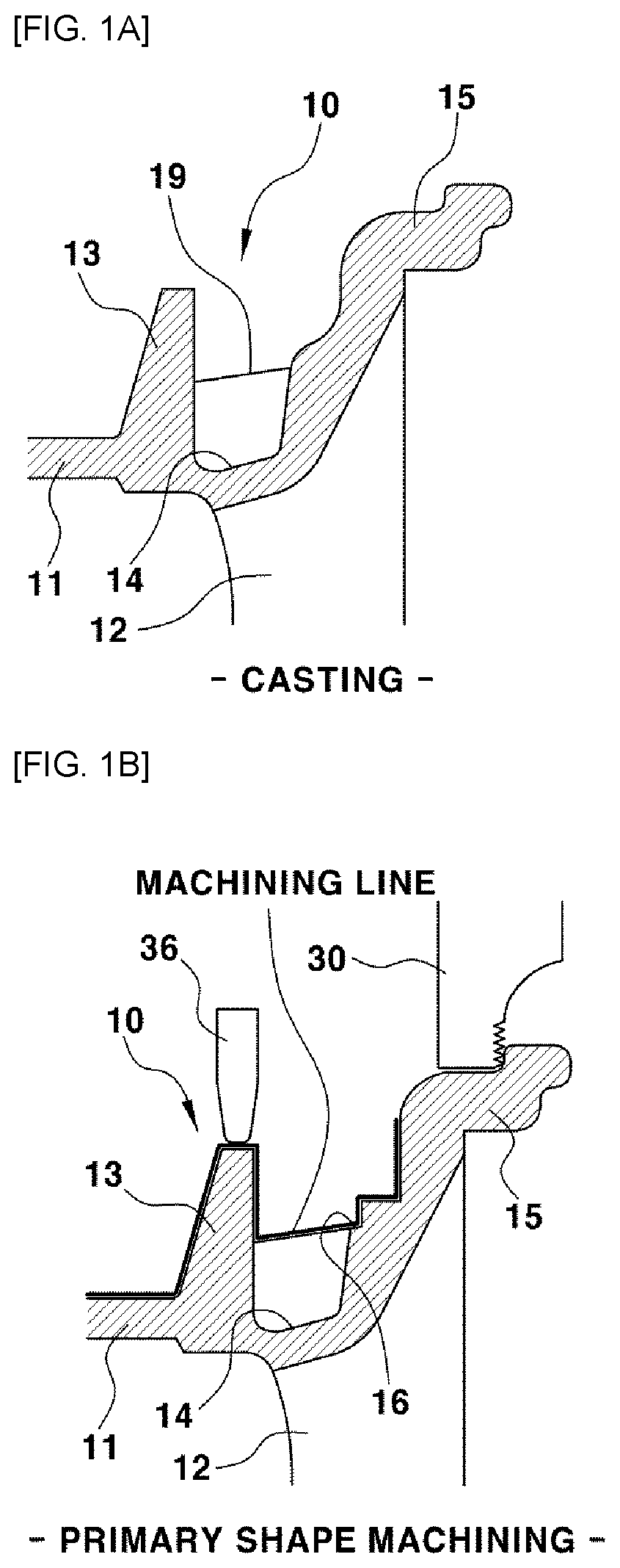
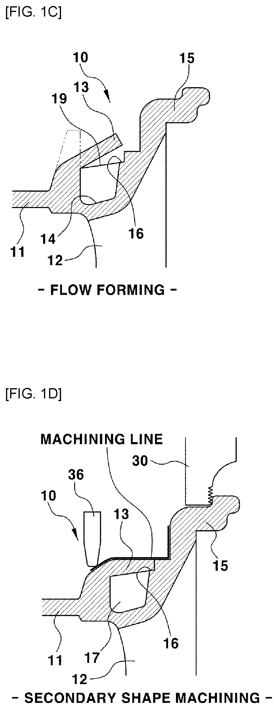
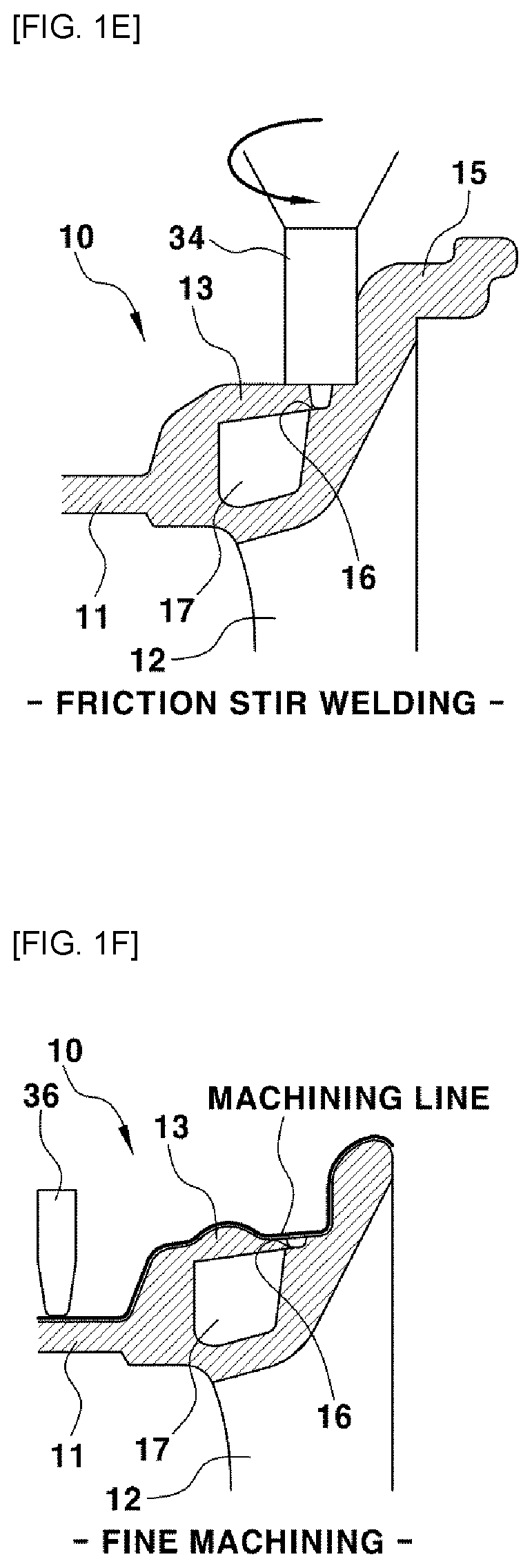
[0036]FIGS. 1A to 1G are enlarged cross-sectional diagrams of main portions sequentially illustrating a process of manufacturing a vehicle wheel according to an exemplary embodiment the present disclosure.

[0037]As illustrated in FIG. 1A, a vehicle wheel 10, which can be manufactured through a casting process according to a predetermined design shape, has a one-piece structure in which a hollow-shaped rim part 11 where tires are mounted and a disc 12 having a spoke are integrated is manufactured through the casting process.

[0038]In addition, when the wheel 10 having the one-piece structure is manufactured through the casting process, a forming end 13 for forming a resonance chamber is integrally formed to protrude from the inner location of the wheel 10 at the boundary between the rim part 11 and the disc 12, a temporary flange 15 to be removed la...


PUM

PropertyMeasurementUnit
Angleaaaaaaaaaa
Diameteraaaaaaaaaa
Lengthaaaaaaaaaa

Abstract

A method for manufacturing a vehicle wheel includes: a casting process of manufacturing the wheel in a one-piece body having a forming end and a temporary flange protruding at inner and outer sides of the wheel, respectively, wherein the one-piece body further includes a resonance chamber forming groove; a primary shape machining process of forming a stepped part at an outer circumferential side of the resonance chamber forming groove; a flow forming process of bending the forming end to be seated on the stepped part; a friction stir welding process of integrally bonding a portion where the forming end and the stepped part are in close contact with each other; a fine machining process of removing the temporary flange;and a sound-absorbing hole machining process of forming a sound-absorbing hole for communicating between the resonance chamber and an interior space of a tire in the forming end.

Description

CROSS-REFERENCE TO RELATED APPLICATION[0001]This application claims the benefit of priority to Korean Patent Application No. 10-2020-0065276 filed on May 29, 2020 in the Korean Intellectual Property Office, the entire contents of which are incorporated herein by reference.TECHNICAL FIELD[0002]The present disclosure relates to a vehicle wheel and a method for manufacturing the same, and more specifically, to a vehicle wheel and a method for manufacturing the same, which may easily machine a hollow resonance chamber, a sound-absorbing hole, and the like after casting a wheel in a one-piece state.BACKGROUND[0003]Road noise during traveling of a vehicle may include resonance sound, booming sound, rumble sound, and the like, and among them, the resonance sound refers to noise which is introduced into the interior through ground, tires, tires-mounted wheels, wheels-mounted chassis parts, and the like.[0004]The wheel, which is also referred to as a road wheel, includes a hollow rim part on...

Claims


Application Information

Patent Timeline
IPC IPC(8): B60B3/02B23K20/12B60B3/06B60B21/02B21D53/30
CPCB60B3/02B23K20/122B23K2101/006B60B21/025B21D53/30B60B3/06B21D22/16B60B2310/202B60B2310/228B60B2310/3025B60B2310/211B60B21/106B60B2900/133B60B2900/116B60B2360/10B60B2900/113B60B2900/112B60B2900/111
Inventor LEE, JUN MINKIM, YOUNG CHANKIM, MIN SOOJO, YOUNG RAEKIM, YOUNG ILPARK, SANG BUMYOO, CHANG HAK
Owner HYUNDAI MOTOR CO LTD
Why Eureka
Try Eureka