
Electronic device and method for controlling transmission power on basis of control information

a technology of electronic devices and control information, applied in power management, amplifier types, amplifiers, etc., can solve problems such as antenna performance degradation, and achieve the effect of reducing antenna performance and transmission power

Pending Publication Date: 2021-12-02
SAMSUNG ELECTRONICS CO LTD
View PDF3 Cites 1 Cited by
  • Summary
  • Abstract
  • Description
  • Claims
  • Application Information

AI Technical Summary

Benefits of technology

The patent aims to reduce the amount of power transmitted during wireless communication based on the frequency band and the electronic device's state. This helps to improve the performance of the antenna while complying with specific absorption rate regulations. In simple terms, the patent aims to optimize wireless communication by adjusting power transmission based on the device and frequency band. This serves to improve the efficiency of the antenna and overall performance of the electronic device.

Problems solved by technology

Since electromagnetic signals may be harmful to a human body, regulatory organizations have prescribed specific absorption rate (SAR) limits for electronic devices.
However, the conventional electronic device reduces the transmission power based only on the frequency band without considering the state of the electronic device, which may cause deterioration in the performance of an antenna when the electronic device is in a specific state.

Method used


Image

  • Electronic device and method for controlling transmission power on basis of control information
  • Electronic device and method for controlling transmission power on basis of control information
  • Electronic device and method for controlling transmission power on basis of control information

Examples


Embodiment Construction

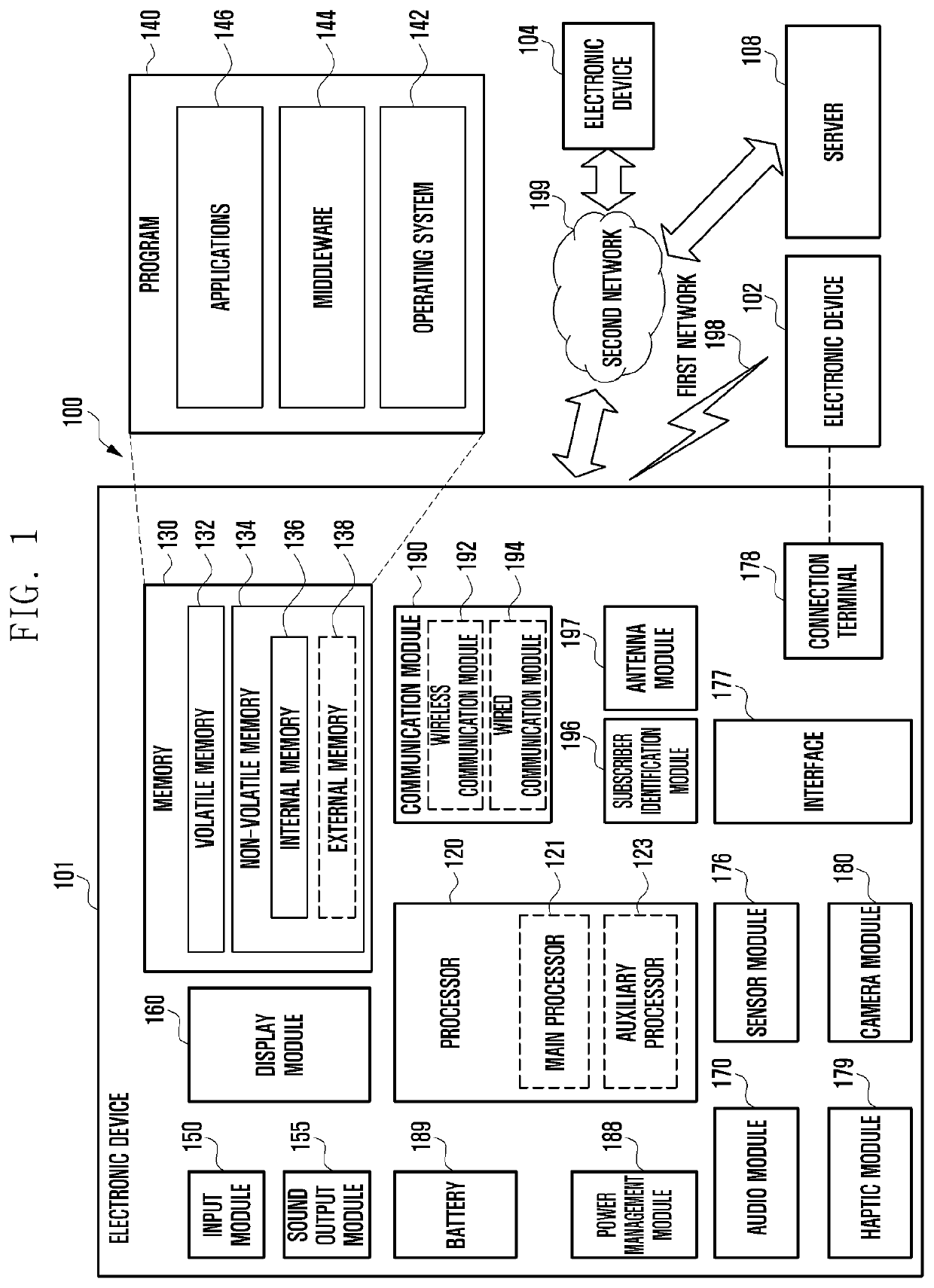
[0019]FIG. 1 is a block diagram illustrating an electronic device 101 in a network environment 100 according to various embodiments. Referring to FIG. 1, the electronic device 101 in the network environment 100 may communicate with an electronic device 102 via a first network 198 (e.g., a short-range wireless communication network), or an electronic device 104 or a server 108 via a second network 199 (e.g., a long-range wireless communication network). According to an embodiment, the electronic device 101 may communicate with the electronic device 104 via the server 108. According to an embodiment, the electronic device 101 may include a processor 120, memory 130, an input device 150, a sound output device 155, a display device 160, an audio module 170, a sensor module 176, an interface 177, a haptic module 179, a camera module 180, a power management module 188, a battery 189, a communication module 190, a subscriber identification module (SIM) 196, or an antenna module 197. In som...


PUM


Abstract

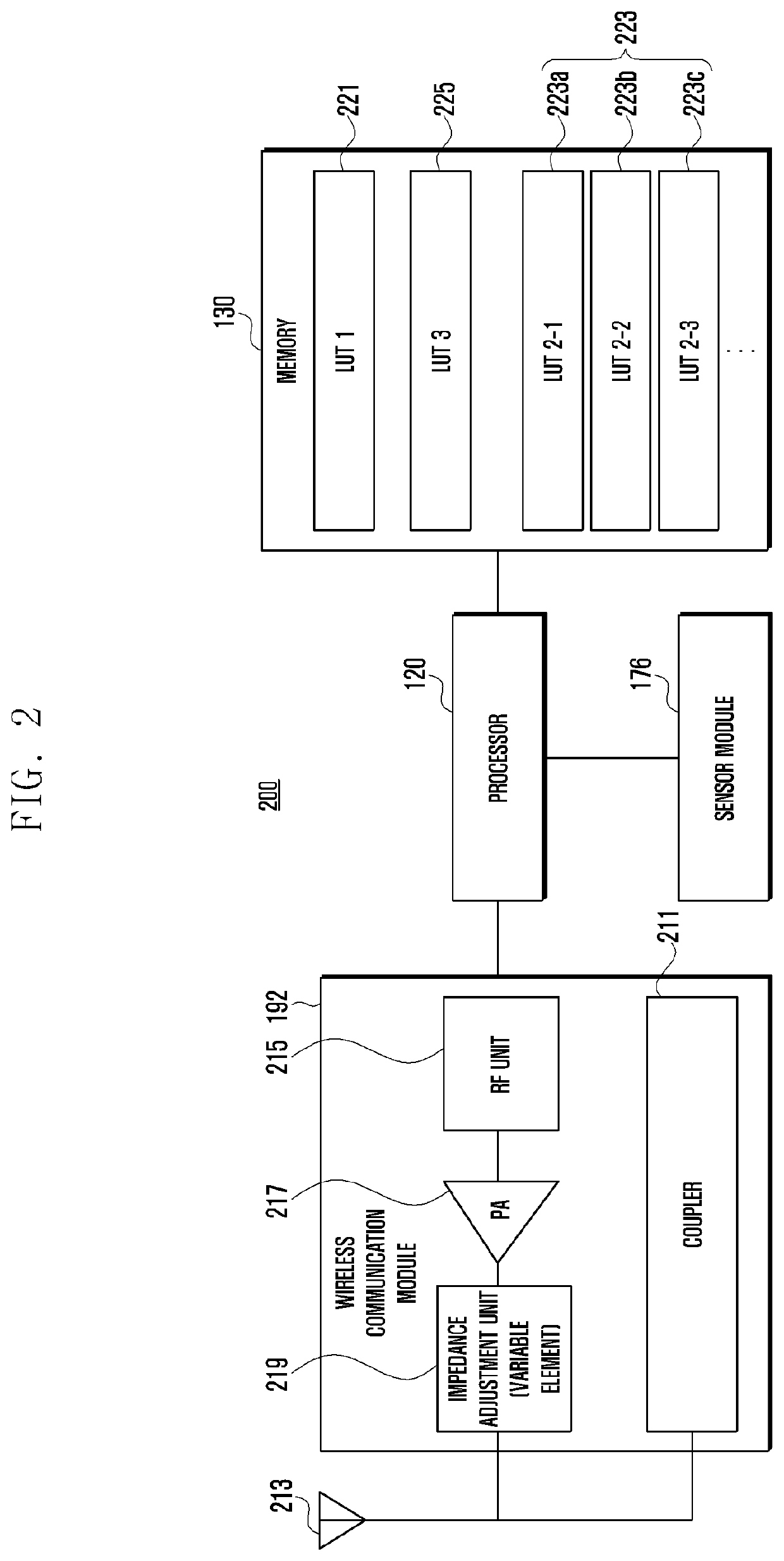
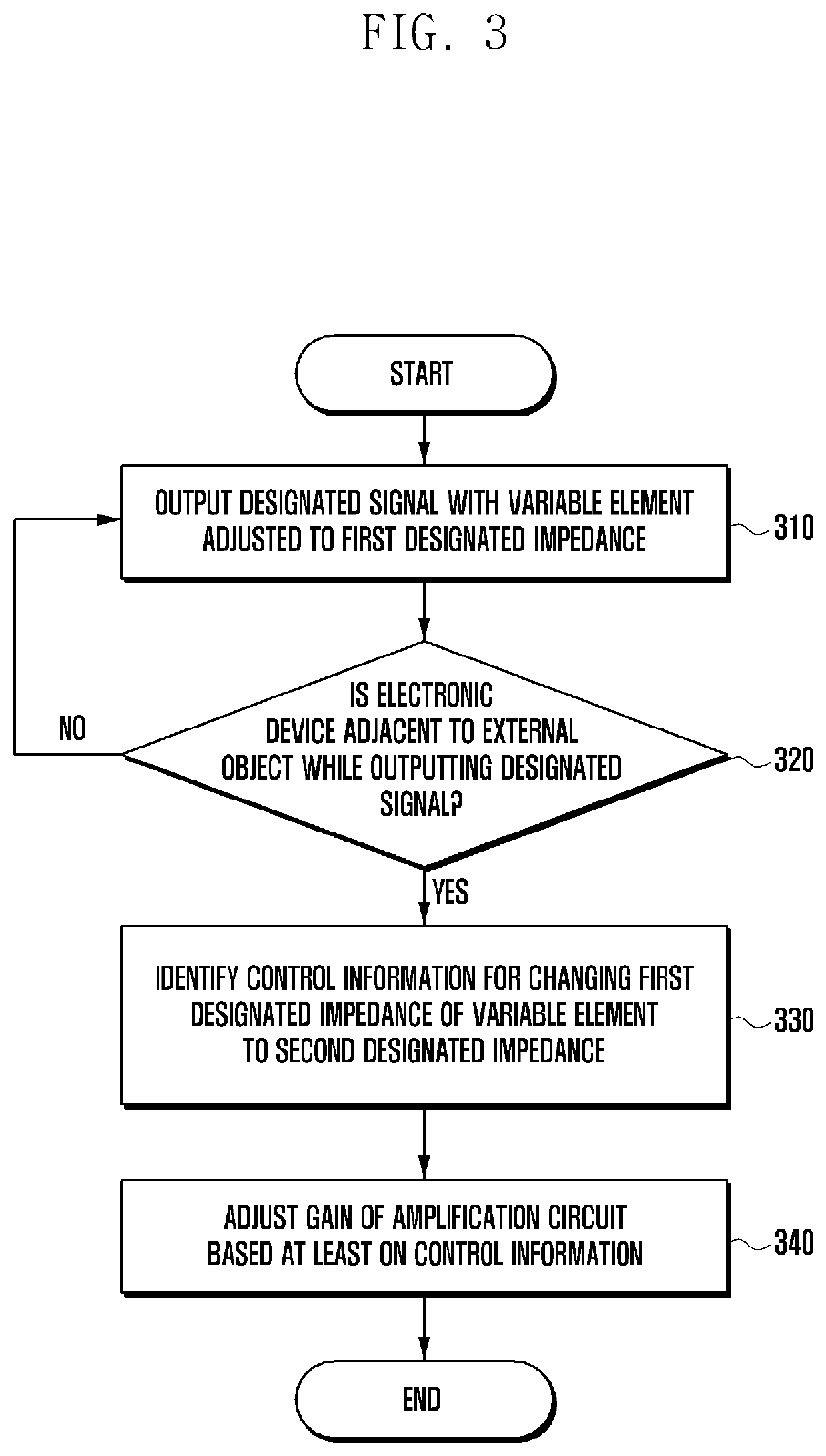
Various embodiments of the present invention relate to an electronic device and a method for controlling transmission power, the electronic device comprising: an amplification circuit; an antenna electrically connected to the amplification circuit; a variable element capable of adjusting the impedance between the amplification circuit and the antenna; and a control circuit, wherein the control circuit can be configured to: output a signal, having been amplified by a designated gain by means of the amplification circuit, to an external electronic device by using the antenna, in a state in which the variable element is adjusted to a first impedance; detect the approach of an external object during outputting of the signal; in response to the detection of the approach of the external object, check control information by which the first impedance of the variable element can be changed to a second impedance; and adjust the designated gain on the basis of at least the control information.

Description

CROSS-REFERENCE TO RELATED APPLICATIONS[0001]This application is a 371 National Stage of International Application No. PCT / KR2019 / 013653 filed Oct. 17, 2019, which claims priority to Korean Patent Application No. 10-2018-0130075 filed Oct. 29, 2018, the disclosures of which are herein incorporated by reference in their entirety.BACKGROUND1. Field[0002]Various embodiments of the disclosure relate to an electronic device and a method for controlling transmission power.2. Description of Related Art[0003]Electronic devices may radiate electromagnetic signals for wireless communication with external devices. Since electromagnetic signals may be harmful to a human body, regulatory organizations have prescribed specific absorption rate (SAR) limits for electronic devices.[0004]An electronic device may reduce transmission power based on the frequency band of wireless communication, thereby performing control to prevent an absorption rate from exceeding a specific prescribed limit.[0005]Howe...

Claims


Application Information

Patent Timeline
Patent Type & Authority Applications(United States)
IPC IPC(8): H04W52/52H04W52/22H03F7/00H03F1/56
CPCH04W52/52H04W52/226H03F2200/451H03F1/56H03F7/00H04B1/3827H04B1/401H03F3/24H04W52/367H04B1/3838
Inventor CHO, WOOSIK
Owner SAMSUNG ELECTRONICS CO LTD
Learn More