Rotary vane internal combustion engine

a technology of internal combustion engine and rotary vane, which is applied in the direction of combustion engine, arcuate-engagement engine, machine/engine, etc., can solve the problems of complicated mechanism for coordinating the movement of the rotor, increase the temperature and wear of the surface so as to facilitate the service, and increase the reliability of the rotary vane internal combustion engin

Inactive Publication Date: 2021-12-09
STANETSKY ANATOLI
View PDF0 Cites 0 Cited by
  • Summary
  • Abstract
  • Description
  • Claims
  • Application Information

AI Technical Summary

Benefits of technology

[0044]Present invention rotary vane internal combustion engine comprising of two nested rotors 3 and 4, wherein each rotor has at least two radial vanes, rigidly attached to the rotor or integrally formed with the rotor, rotates within the cylindrical cavity of the housing 9 to form at least four chambers in which occurs the intake I, compression C, combustion S and exhaustion E. The nested rotors assembled as one part, wherein each one side of the vanes are closed by rigidly mounted side washer 5 that eliminates need to seals of the chambers. Each nested rotor 3 and 4, alternately engages with an axial shaft 1 by means of overrunning one-way clutches 8, which ensures its continuous rotation by attaching one rotor and free passing through the other rotor, and in contrary. To avoid the reverse rotation of rotors 3 and 4 and ensure continuous, smooth rotation of shaft 1 applied the adjustable flywheels 12, which are connected with unlocked rotor through holding cushi

Problems solved by technology

Current designs of rotary vane internal combustion engines have serious disadvantages: complicated mechanisms for coordinating movement of the rotors (vanes), increased temperature and wear of surfaces due to friction, availability of reciprocation of working elements.
However, such a rotary machine described a mechanism for converting the movement of vanes still has large dimensions.
Not eliminated the alternating shock loads because do not provide guaranteed gap acceleration and deceleration of working rotors.
Disadvantages of this rotary machine and this type of rotary engines are related to difficulties removing the power from two different shafts, each connected to its communication mechanism with vanes that move irregularly and impulsively.
Removing power from such shafts of the proposed method is extremely difficult.
The required approval of their motion relative to each other is performed using extremely complex and cumbersome mechanism for synchronization.
The huge inertial loadings destroy the applied mechanisms of coordination of rotation shafts and related rotor vanes.
And serious problem of the engine is the seal of clearances and lubrication of working surfaces of the rotor vanes.
A problem with some prior art rotary vane machines is that they cannot successfully operate under high pressure and heat.
This is inability to operate under high pressure and heat due to poor seals on the vanes and high torque on the vanes.
In addition, the vanes have a return-translational movement that aggravates the operation of the mechanism and at high temperatures will jam.
Intake, exhaust, and ignition systems provide a combustion cycle for each chamber as the rotor orbits and cannot be cooled and cannot readily be lubricated so is very susceptible to overheating, which keeps it from being usable, and can't eliminate the reciprocating movement of the vanes.
In one embodiment means are provided to vary the compression and expansion ratios, and cannot be cooled and cannot readily to be lu

Method used


Image

  • Rotary vane internal combustion engine
  • Rotary vane internal combustion engine
  • Rotary vane internal combustion engine

Examples


Embodiment Construction

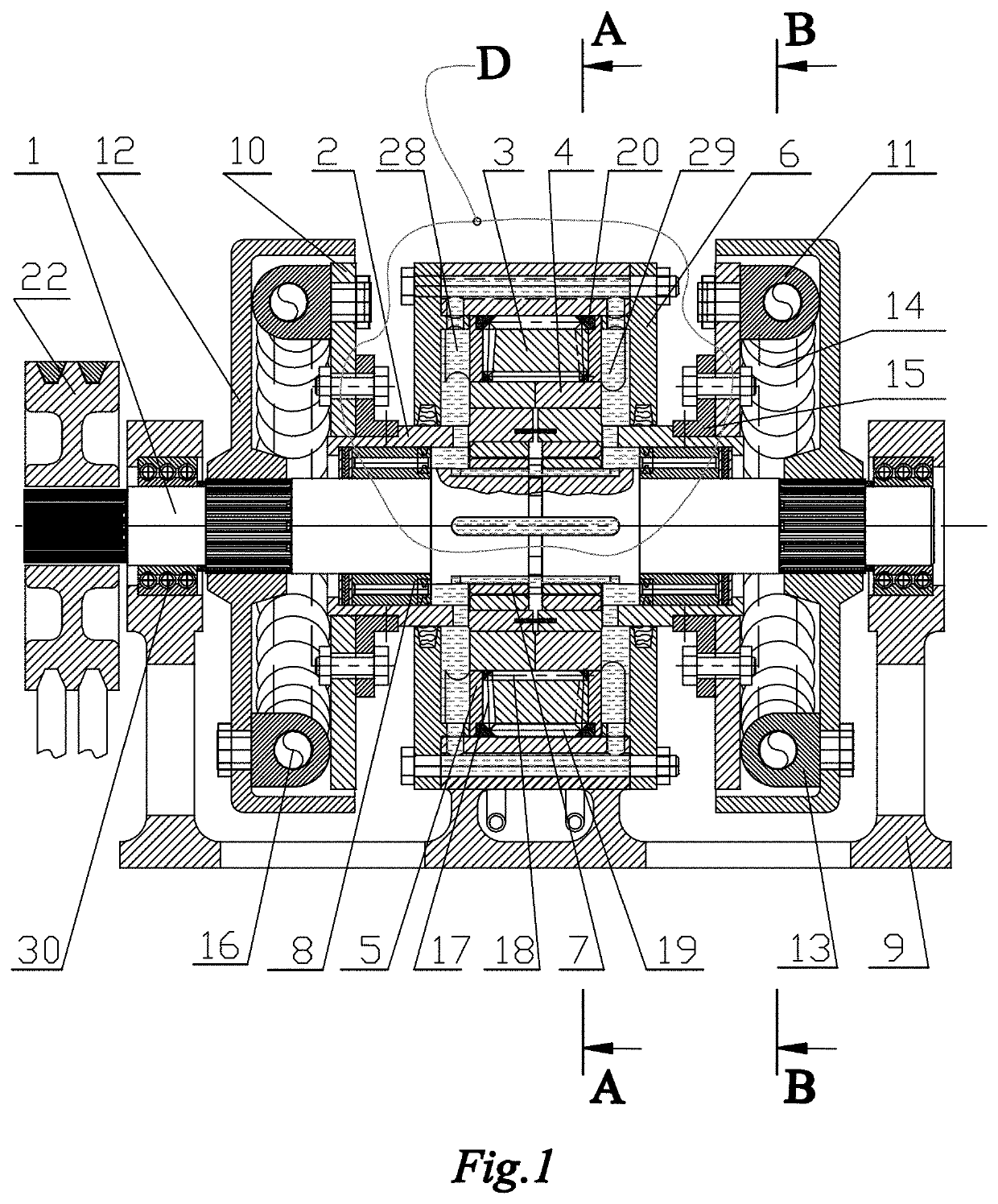
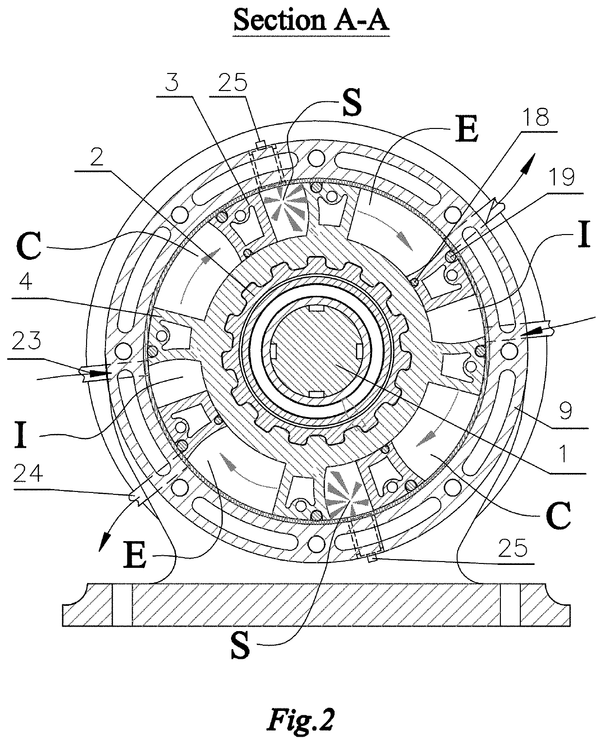
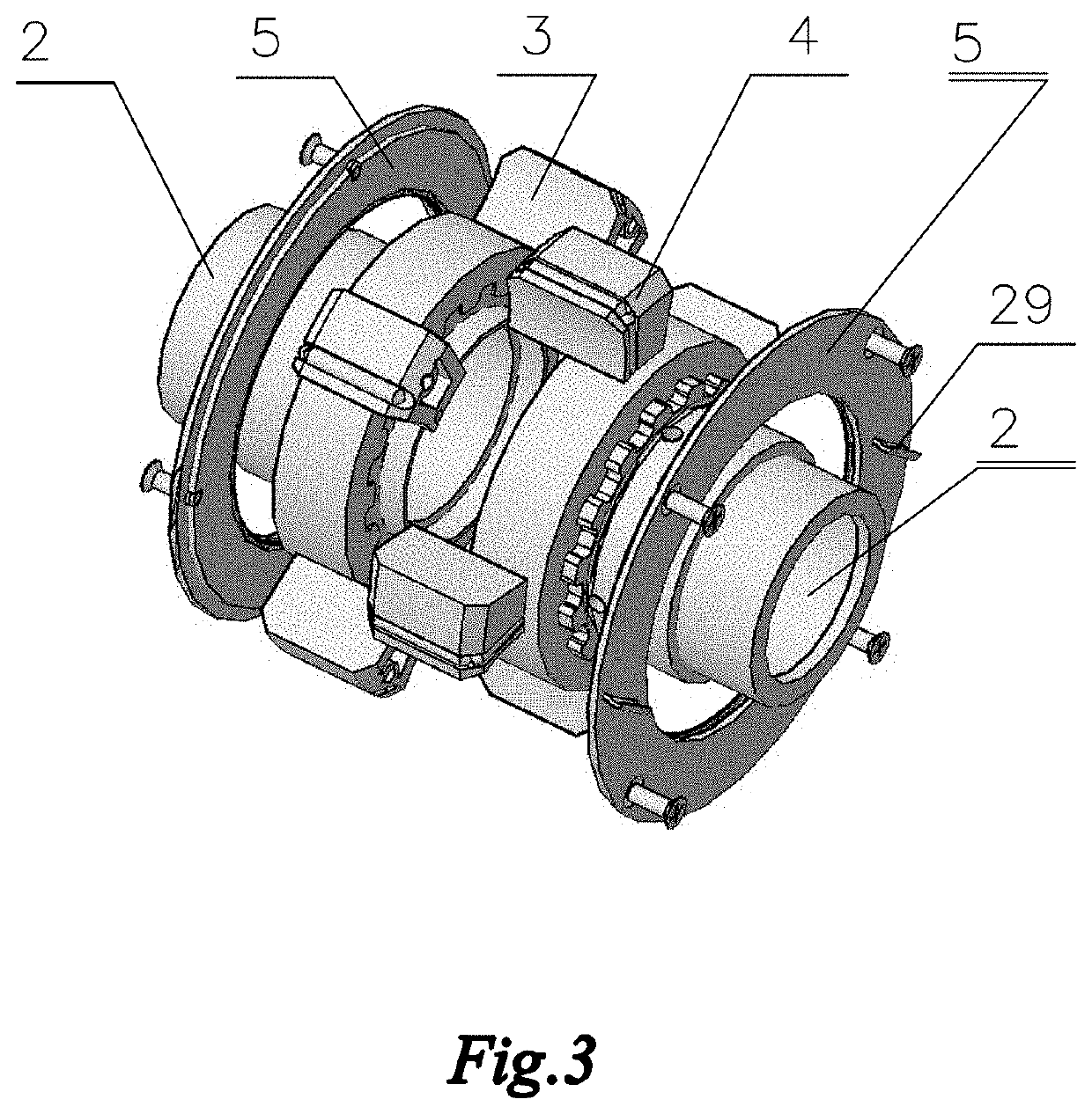
[0061]The present invention is one embodiment of a rotary vane internal combustion engine where torque on the shaft is produced due to alternating interaction of the rotors within. The rotors placed in housing between two cooling chambers, around which cooling fluid is circulated, have conical and cylindrical graphite seals to eliminate friction between the work surfaces. This invention relates to improvement of rotary vane internal combustion engine and will be described with reference to the following drawings.

[0062]As shown on the drawing FIG. 1, rotary vane internal combustion engine related to one embodiment of the present invention comprising a housing 9, inside which set a shaft 1, which interacts with rotors 3 and 4 through one-way overrunning clutches 8, which are rigidly joined with rotors 3 and 4 by adapters 2. The one side of each rotor is rigidly closed by flanges 5, which are formed with caps 6 the chambers for circulation the cooling fluid to use mounted on flanges 5 ...


PUM


Abstract

Rotary vane internal combustion engine comprises of two rotors, nested in each other, placed in a cylindrical housing, wherein each rotor has at least two radial vanes rigidly attached to the rotor that form chambers for intake, compression, combustion, and exhaust. Each rotor, alternately engages with a shaft by overrunning one-way clutches and held from turning back, through the cushioning mechanisms, mounted on flywheels, which are rigidly attached on the shaft, wherein the assembled rotors from the outside are rigidly closed by flanges on each of which is mounted at least one blade, which are placed into formed cavity between rotors and caps of the housing thereby forming two cooling chambers through which coolant circulates around rotors through openings in the housing and through longitudinal grooves in the shaft. On the vanes mounted cylindrical and conical seals that exclude the need for lubrication.

Description

CROSS-REFERENCE TO RELATED APPLICATIONS[0001]International Classification: F01C1 / 02, F01C1 / 08, F01C1 / 22, F01C1 / 24; F01C1 / 063; F02B 53 / 00; F02B 55 / 00; F02B053 / 00;[0002]Current U.S. Classification: 123 / 18.00R, 41 R, 192.1, 143 R+, 200, 213, 215, 217, 222, 227 234, 237, 242, 245, 239, 293, and 306; 356 / 216; 418 / 13, 33, 89, 93, 99, 147, 156, 268; 61 / 187,866; 74 / 437;[0003]Class Search: 60 / 597,616; 61 / 187,866; 123 / 18.00R, 41 R, 192.1, 143 R+, 200, 204, 213, 215, 217, 222, 243, 231, 236, 237, 242, 239, 293, 306, 568; 384 / 99, 109, 111; 418 / 13, 33, 36, 89, 91, 92, 93, 97, 98, 129, 138, 141, 143, 147, 156, 268;STATEMENT ABOUT FEDERALLY SPONSORED RESEARCH OR DEVELOPMENT[0004]Not ApplicableTHE NAMES OF THE PARTIES TO A JOINT RESEARCH AGREEMENT[0005]Not ApplicableINCORPORATION-BY-REFERENCE OF MATERIAL SUBMITTED ON A COMPACT DISC OR AS A TEXT FILE VIA THE OFFICE ELECTRONIC FILING SYSTEM (EFS-WEB)[0006]Not ApplicableSTATEMENT REGARDING PRIOR DISCLOSURES BY THE INVENTOR OR A JOINT INVENTOR[0007]Not...

Claims


Application Information

Patent Timeline
IPC IPC(8): F02B55/02F02B55/10F02B53/10F02B55/14F01C21/06F01C21/00F01C1/02
CPCF02B55/02F02B55/10F02B53/10F01C1/02F01C21/06F01C21/008F02B55/14F01C1/063Y02T10/12
Inventor STANETSKY, ANATOLI
Owner STANETSKY ANATOLI
Why Eureka
Try Eureka