
Apparatus for transferring electrical power to an electrical load with converter

Active Publication Date: 2021-12-16
EGGTRONIC ENG SPA
View PDF0 Cites 0 Cited by
  • Summary
  • Abstract
  • Description
  • Claims
  • Application Information

AI Technical Summary

Benefits of technology

The present invention aims to solve or significantly reduce the problems of the prior art, by providing a simple and low-cost solution. The technical effect of this invention is to provide a more efficient and cost-effective solution to overcome the current limitations of the prior art.

Problems solved by technology

However, all AC / DC converters can have the drawback that the active switches (e.g. MOSFET) present in the wave generator, especially when the latter is made in the form of a resonant circuit, can be subjected to extremely high voltages.
Active switches capable of withstanding these voltage levels are generally not very common on the market, relatively very expensive, bulky and low-performance in terms of maximum switching frequencies, with the result of obtaining a large, expensive and less efficient converter than what is theoretically possible.
Some known solutions tackle this drawback by stacking a series of active switches, with consequent probable increase in costs, greater difficulty of controlling the active switches and more space occupied.
Another drawback of the AC / DC converters outlined above consists of the fact that they implement highly non-linear circuits, the control of which is made generally very difficult since there are only a few controllable variables without compromising the energy efficiency of the system.
Hence these AC / DC converters are very rigid and difficult to adjust, for example to deal with possible variations of the input voltage (different countries can have distribution networks at different voltage values), to deal with possible variations of power absorption by the electrical load, or to deal with possible tuning variations linked to the component not being ideal in the case of resonant circuits.
A further drawback consists of the fact that, between the rectifier and the wave generator, the primary circuit generally comprises a filtering capacity having the function of levelling and stabilising the shape of the voltage in output from the rectifier, so as to apply a voltage that can be approximated to a direct voltage in input to the high-frequency wave generator.
Being subjected to high voltage values, this filtering capacity is generally physically large and constitutes a substantial constraint both in terms of costs and in terms of space occupied by the converter.
Moreover, this filtering capacity determines the further drawback of worsening the Power Factor of the converter, since it determines an impulsive absorption that it is often necessary to correct with further Power Factor Correction (PFC) stages.

Method used


Image

  • Apparatus for transferring electrical power to an electrical load with converter
  • Apparatus for transferring electrical power to an electrical load with converter
  • Apparatus for transferring electrical power to an electrical load with converter

Examples


Embodiment Construction

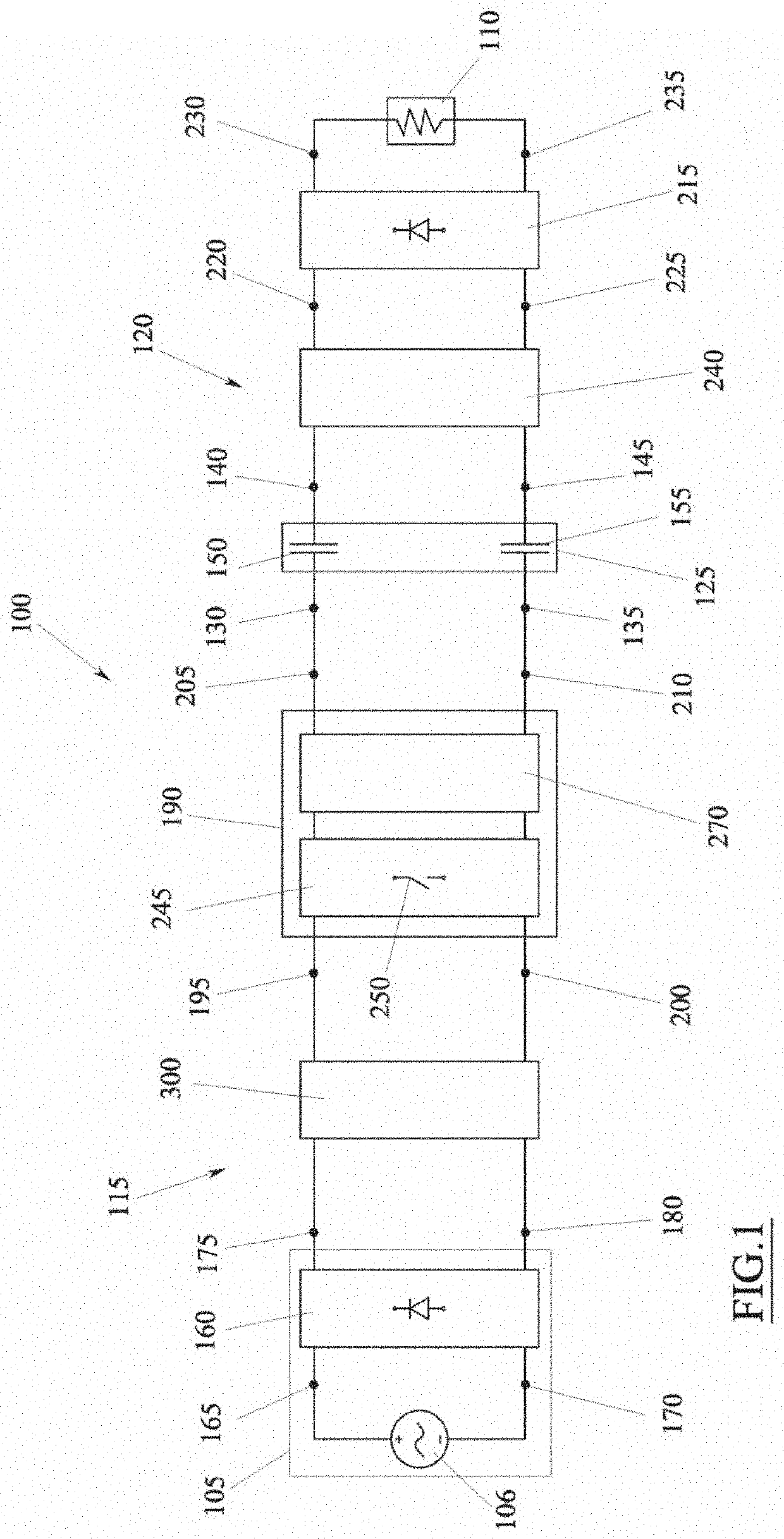
[0117]An embodiment of the present invention provides an apparatus 100 for transferring electrical power from an electrical source 105 to an electrical load 110.

[0118]The electrical source 105 is generally a source of direct voltage or comparable to a direct voltage.

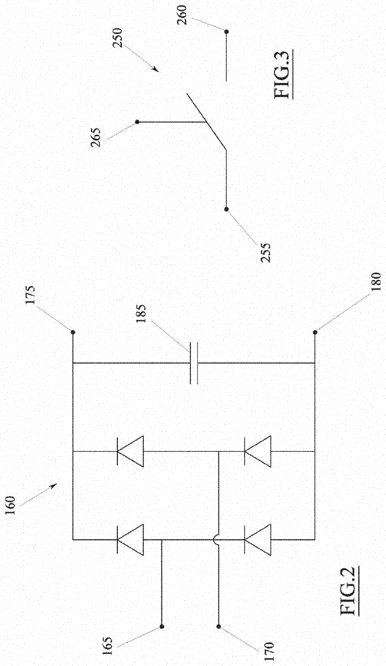
[0119]In accordance with the illustrated example, the electrical source 105 can comprise a rectifier, globally indicated with 160, which is adapted for receiving in input an alternating voltage coming from a source of alternating voltage 106, for example a common electrical distribution network, for converting (rectifying) said alternating voltage into a direct voltage (or comparable to a direct voltage) and for outputting said direct voltage.

[0120]The source of alternating voltage 106 can be adapted for supplying an alternating voltage of variable value depending on the country or the use (e.g. industrial or domestic).

[0121]Purely as an example, the source of alternating voltage 106 can be a 50-60 Hz, 90-250V AC network...


PUM


Abstract

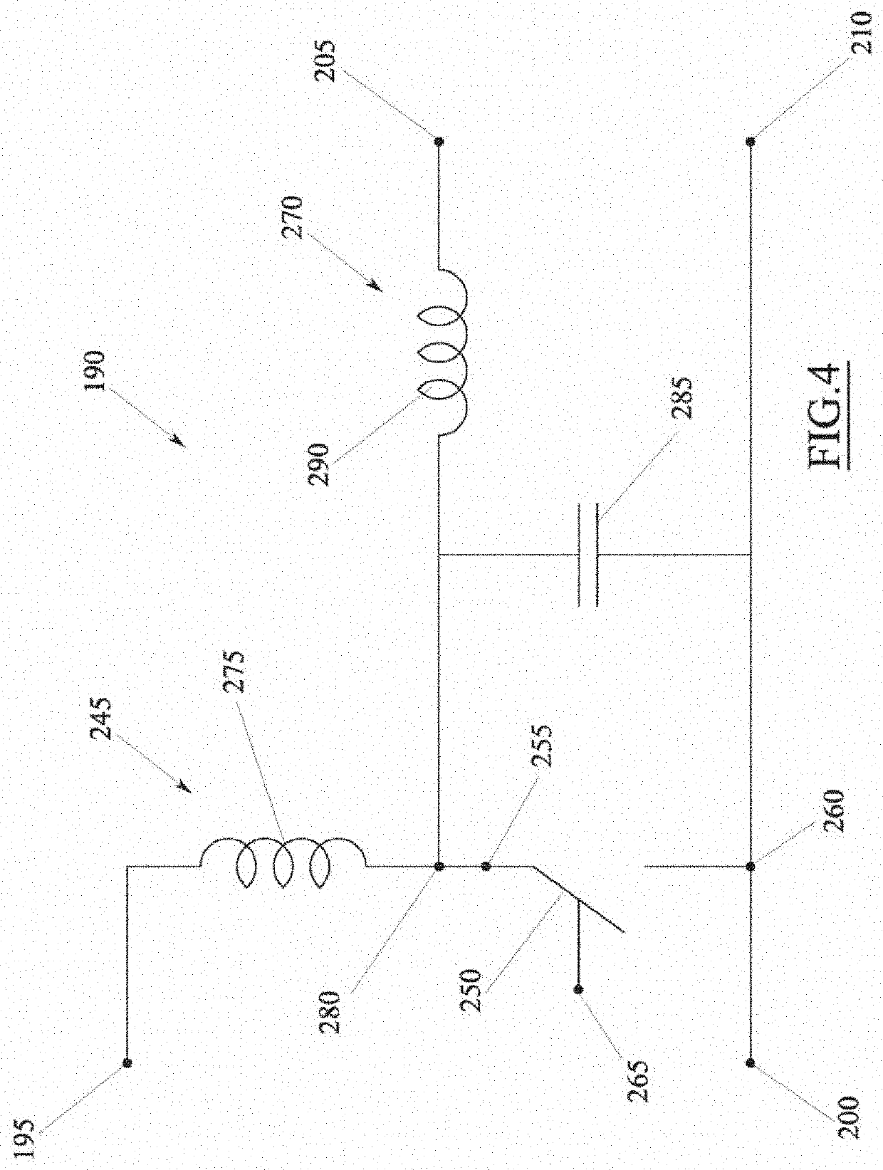
The invention describes an apparatus (100) for transferring electrical power to an electrical load (110), comprising: a primary circuit (115), an electrical source (105) adapted for supplying said primary circuit with a direct input voltage, a secondary circuit (120) adapted for feeding the electrical load (110), and a coupling device (125) adapted for transferring electrical power from the primary circuit (115) to the secondary circuit (120), wherein the primary circuit (115) comprises: a converter (300) adapted for receiving the input voltage, for modifying said input voltage and for outputting said modified voltage, and a wave generator (190) comprising at least one switching circuit provided with at least one active switch (250), which is adapted for receiving in input the modified voltage in output from the converter (300), for converting said modified voltage into voltage waves and for applying said voltage waves to said coupling device (125), and wherein said converter comprises at least one active switch (315) adapted for selectively allowing or preventing the passage of electrical current from the electrical source (105) to the wave generator (190).

Description

TECHNICAL FIELD[0001]The present invention concerns an apparatus for transferring electrical power to an electrical load. The electrical load can for example be any electrical or electronic device that must be fed electrically to allow the operation thereof and / or to charge the inner batteries of the device itself. Classic examples of this type of electrical / electronic devices include, but are not limited to, smartphones, computers, laptops, tablets, television sets, domestic appliances, automated systems, servers and many other similar devices.PRIOR ART[0002]A solution currently very widely used for transferring electrical power to an electrical load is that of using an AC / DC converter, which is capable of converting an alternating voltage (AC), generated for example by a common electrical distribution network (e.g. 50-60 Hz, 90-250V AC), into a direct voltage (DC) suitable for feeding the electrical load.[0003]AC / DC converters generally comprise a primary circuit, typically connec...

Claims


Application Information

Patent Timeline
IPC IPC(8): H02J50/05H02M3/158
CPCH02J50/05H02M3/1582H02M3/156
Inventor SPINELLA, IGORDENTE, ENRICOMASCIA, GIOVANNI
Owner EGGTRONIC ENG SPA
Learn More