
System for transferring electrical power to an electrical load

a technology of electrical power and electrical load, applied in the direction of climate sustainability, power electronics conversion, amplifier with semiconductor devices/discharge tubes, etc., can solve the problems of reducing efficiency and increasing the space occupied by the circui

Active Publication Date: 2022-01-06
EGGTRONIC ENG SPA
View PDF3 Cites 0 Cited by
  • Summary
  • Abstract
  • Description
  • Claims
  • Application Information

AI Technical Summary

Benefits of technology

The present invention aims to solve or reduce the problems of the prior art by providing a simple, rational, and cost-effective solution. The technical effect of this invention is to solve or reduce the issues of the prior art, such as improving efficiency, reducing complexity, or enhancing performance.

Problems solved by technology

One of the few drawbacks of this architecture is, however, represented by the need to place a choke inductance of great value between the feed voltage of the circuit and the active switch.
The presence of this large choke inductance, through which the currents useful for feeding the load flow, substantially increases the space occupied by the circuit and, due to the parasitic phenomena typical of real inductances, like for example magnetic hysteresis, the eddy currents in the magnetic materials, the skin effect and the Joule effect, substantially reduces the efficiency thereof.

Method used


Image

  • System for transferring electrical power to an electrical load
  • System for transferring electrical power to an electrical load
  • System for transferring electrical power to an electrical load

Examples


Embodiment Construction

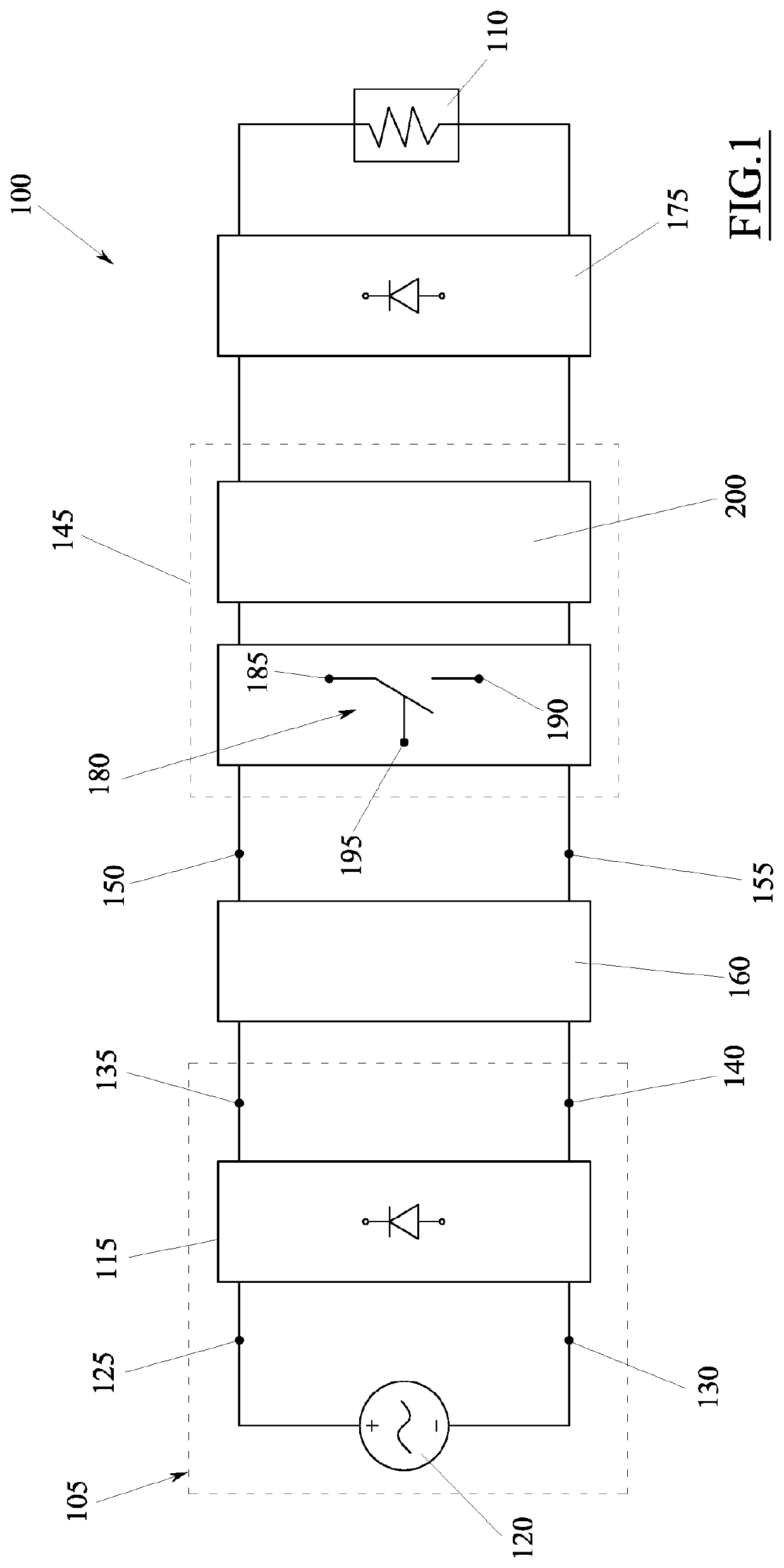
[0096]An embodiment of the present invention provides a system 100 for transferring electrical power from a direct electrical voltage source 105, or at least comparable to a direct voltage, to an electrical load 110.

[0097]The electrical load 110, which is generically represented with the symbol of an electrical resistance, can be any electric or electronic device that must be fed electrically to allow the operation thereof and / or to charge the internal batteries of the device itself.

[0098]Classic examples of electric / electronic devices of this type are computers, tablets, smartphones, television sets, domestic appliances, automated systems, servers and many others.

[0099]In some embodiments, the direct voltage source 105 can be a generator of direct voltage or a battery.

[0100]In other embodiments, the direct voltage source 105 can on the other hand comprise a rectifier 115 adapted for receiving in input an alternating voltage coming from an alternating voltage source 120, for convert...


PUM


Abstract

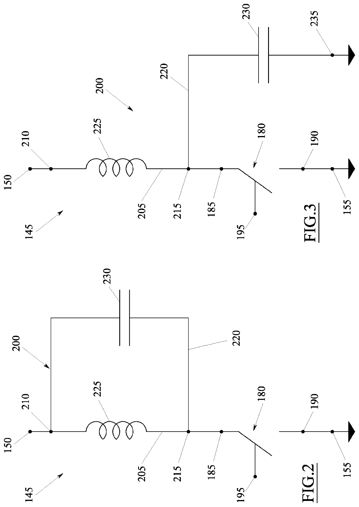
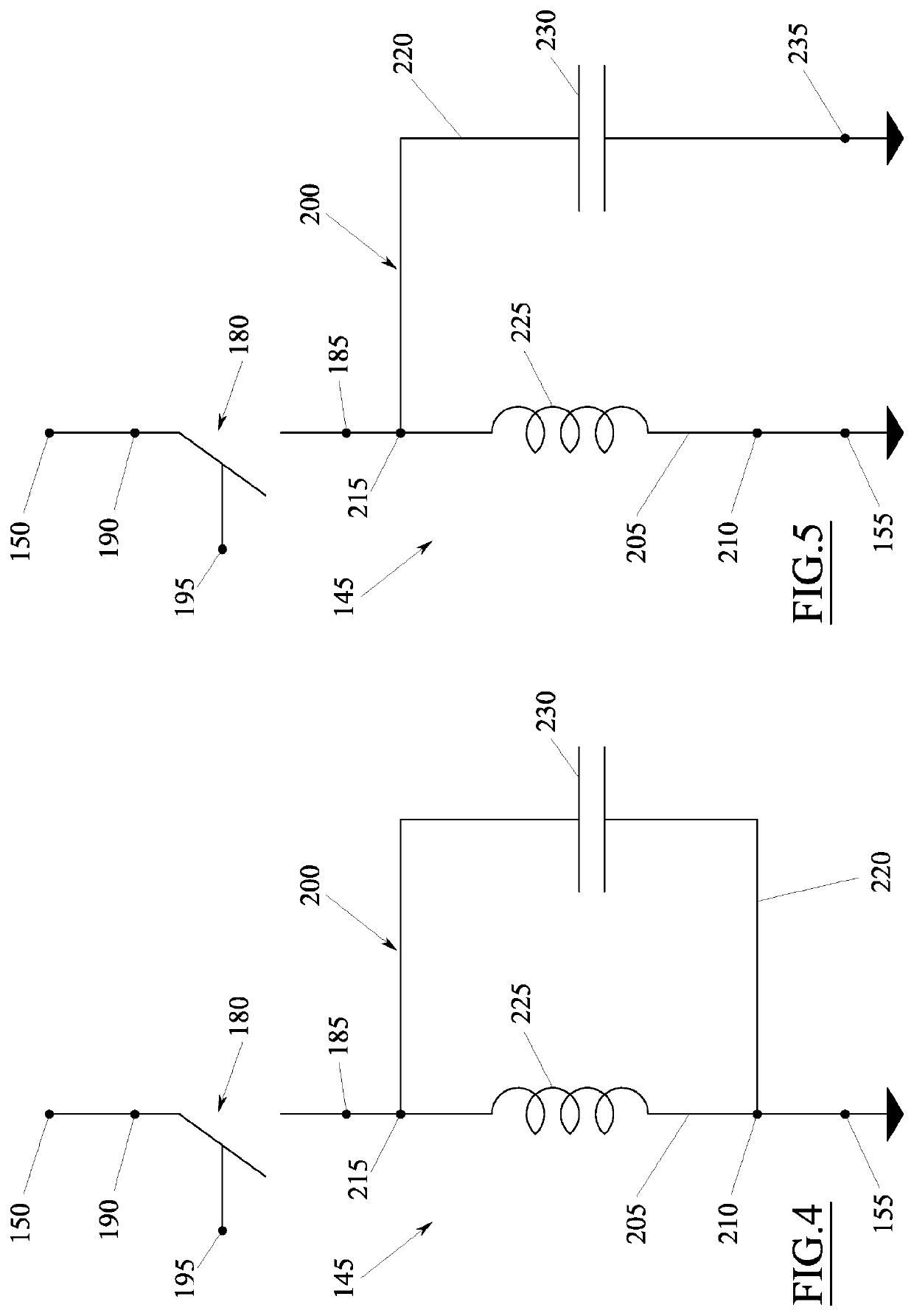
The invention describes a system (100) for transferring electrical power to an electrical load (110), comprising: a direct electrical voltage source (105), and at least one wave generator (145) adapted for converting the direct electric voltage into voltage waves to be transmitted to the electrical load (110); wherein said wave generator (145) comprises at least: an active switch (180) provided with two connection terminals (185, 190) and adapted for being controlled by an electric control signal between a saturation condition, in which it allows the passage of electrical current between said connection terminals (185, 190), and a prevention condition, in which it prevents said passage of electrical current, and a resonant circuit (200) sized to reduce the electrical power applied to said active switch (180) in the moments in which said active switch switches from the saturation condition to the prevention condition and vice-versa; and wherein said resonant circuit (200) comprises at least: a central electrical node (215) to which a first connection terminal (185) of the active switch (180) is connected, a first electrical branch (205) extending between said central electrical node (215) and a first terminal (210), a second electrical branch (220) extending between said central electrical node (215) and the first terminal (210) or between said central electrical node (215) and a further terminal (235) connected to a reference voltage, a resonance inductance (225) arranged on the first electrical branch (205), and a resonance capacity (230) arranged on the second electrical branch (220).

Description

TECHNICAL FIELD[0001]The present invention concerns a system for transferring electrical power to an electrical load. The electrical load can for example be any electrical or electronic device that must be fed electrically to allow the operation thereof and / or to charge the inner batteries of the device itself. Classic examples of this type of electrical / electronic devices include, but are not limited to, smartphones, computers, laptops, tablets, television sets, domestic appliances, automated systems, servers and many other similar devices.PRIOR ART[0002]A solution currently very widely used for transferring electrical power to an electrical load is that of using a converter, i.e. an electric circuit configured so as to transform an input voltage into a voltage suitable for feeding the load.[0003]For example, there are known AC / DC converters adapted for transforming an alternating voltage into a direct voltage, DC / AC converters adapted for transforming a direct voltage into an alte...

Claims


Application Information

Patent Timeline
Patent Type & Authority Applications(United States)
IPC IPC(8): H02M7/537H02J50/12
CPCH02M7/537H02J50/12H02J50/05H02J50/10H03F3/2176Y02B70/10H02M1/0058H02M1/348H02M1/346
Inventor SPINELLA, IGORDENTE, ENRICOMASCIA, GIOVANNI
Owner EGGTRONIC ENG SPA
Learn More