
Magnetic separators with stationary magnetic matrices, and methods of using the same

Active Publication Date: 2022-01-20
RIBEIRO CLÁUDIO HENRIQUE TEIXEIRA +1
View PDF0 Cites 0 Cited by
  • Summary
  • Abstract
  • Description
  • Claims
  • Application Information

AI Technical Summary

Benefits of technology

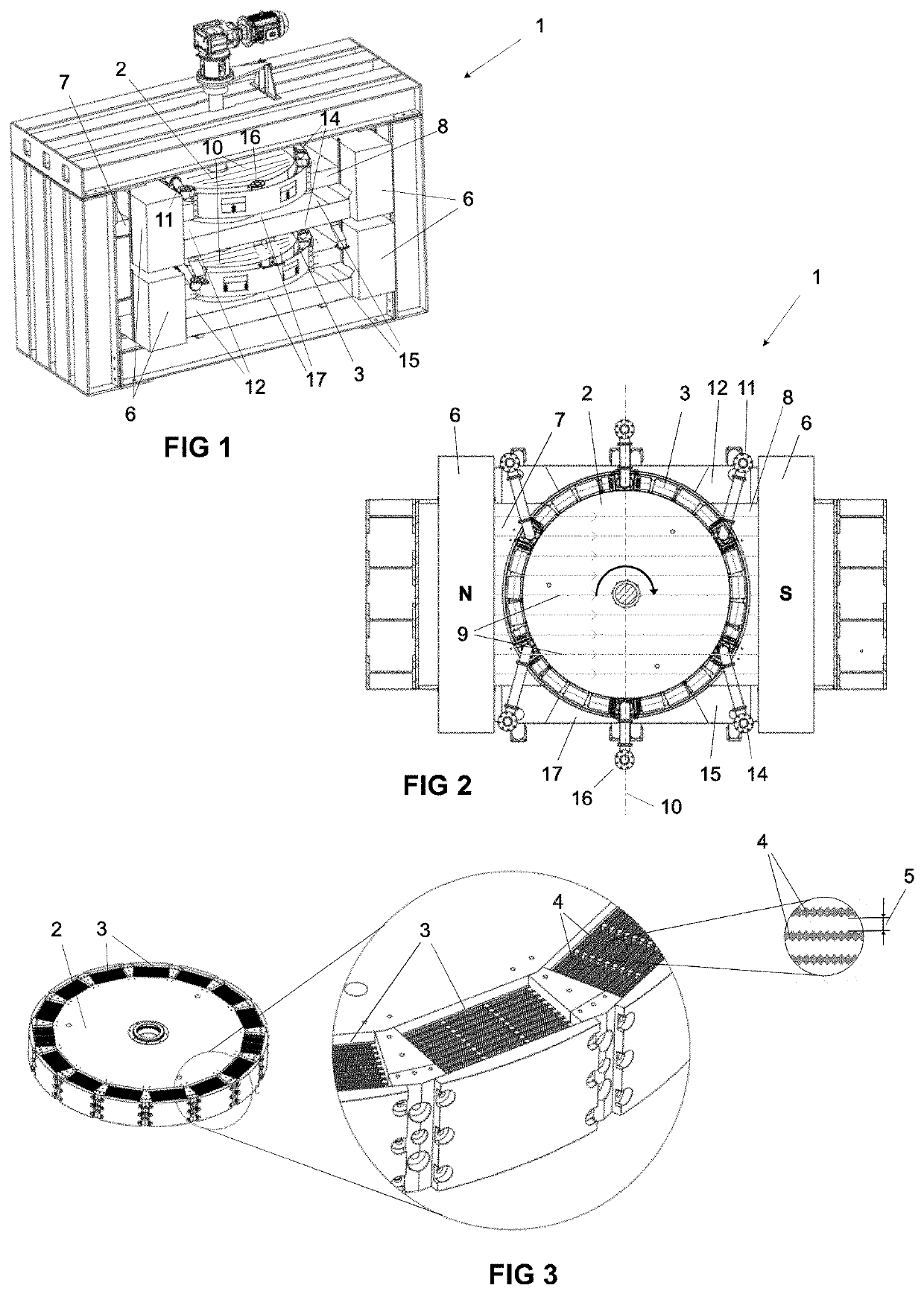
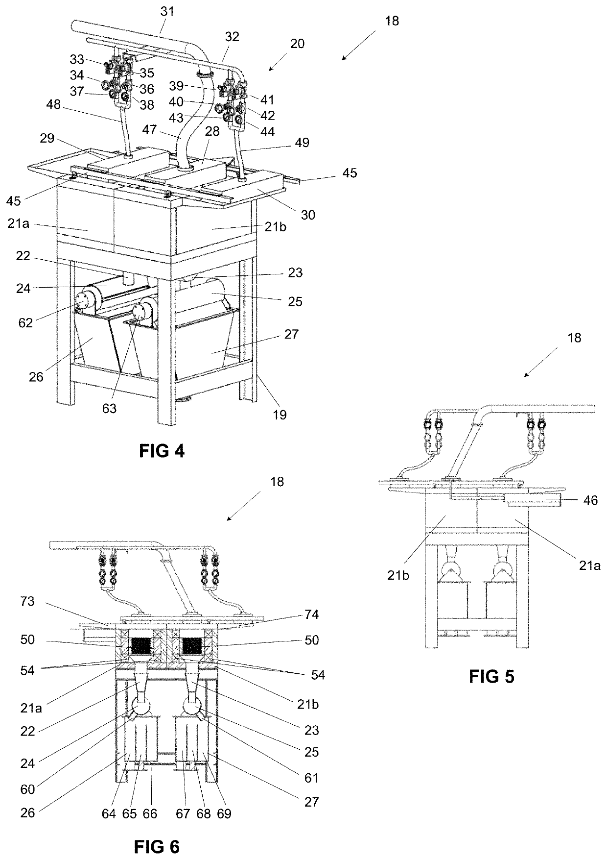
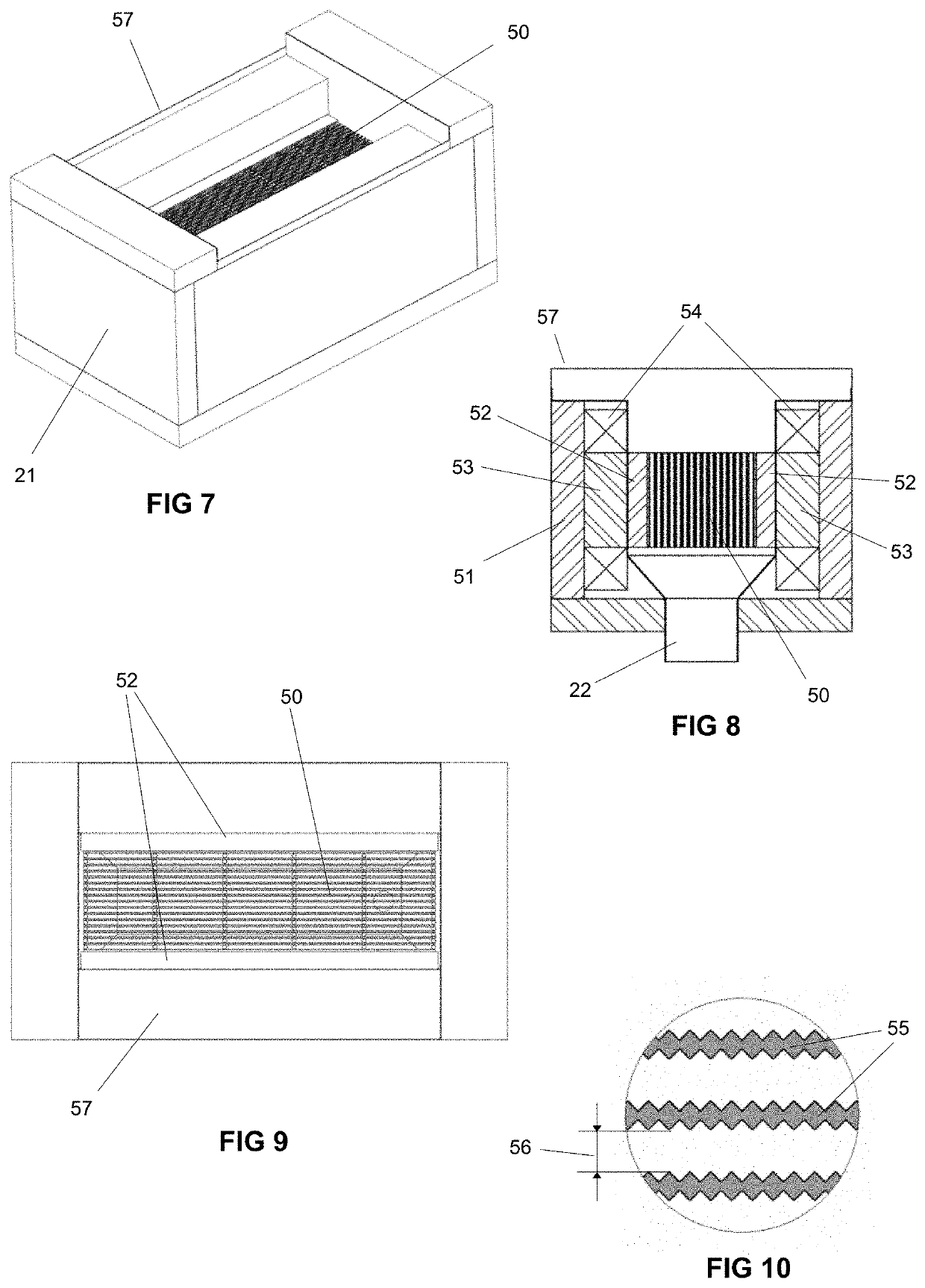
The patent describes a system that includes two magnetic sieves for separating magnetic and non-magnetic components in a material feed flow. The system has a controller that can control the power supply to the magnetic sieves to regulate the magnetic field. Before switching the material flow from one magnetic sieve to the other, the controller increases the power supply to the other magnetic sieve to generate a magnetic field for separating magnetic and non-magnetic components. After switching the material flow, the controller decreases the power supply to the one magnetic sieve to reduce the magnetic field for purging magnetic components. The system also includes two funnels connected to the magnetic sieves for creating a negative pressure differential to promote the flow of material feed flow through the magnetic sieve. The technical effects of this system include improved separation efficiency and simplified purging process.

Problems solved by technology

Though conventional magnetic separators have proven effective, they nonetheless present a number of inefficiencies and shortcomings.
For example, rotation of the rotors through the magnetic field in those conventional systems requires high precision motors, gearboxes, and shafts; and places a high work load on those components with large power consumption, investment, and maintenance costs.
In addition, those conventional systems are generally made with the magnetic matrices integrally mounted in the rotor, which makes it difficult, if not impossible, to make mechanical adjustments to the matrices to adapt the system to changing operational circumstances.

Method used


Image

  • Magnetic separators with stationary magnetic matrices, and methods of using the same
  • Magnetic separators with stationary magnetic matrices, and methods of using the same
  • Magnetic separators with stationary magnetic matrices, and methods of using the same

Examples


Embodiment Construction

[0056]The following disclosure discusses the present invention with reference to the examples shown in the accompanying drawings, though does not limit the invention to those examples.

[0057]The use of any and all examples, or exemplary language (e.g., “such as”) provided herein is intended merely to better illuminate the invention and does not pose a limitation on the scope of the invention unless otherwise claimed. No language in the specification should be construed as indicating any non-claimed element as essential or otherwise critical to the practice of the invention. Unless made clear in context,

[0058]As used herein, the singular forms “a,”“an,” and “the” include plural referents unless the context clearly dictates otherwise. Unless indicated otherwise by context, the term “or” is to be understood as an inclusive “or.” Terms such as “first”, “second”, “third”, etc. when used to describe multiple devices or elements, are so used only to convey the relative actions, positioning ...


PUM


Abstract

A magnetic separator and methods of use are provided for continuous feeding of a material feed flow at high production feed rates without rotation of large heavy steel parts through high intensity magnetic fields. The magnetic separators use stationary magnetic matrices and redirect a material feed flow and a flushing fluid flow between the stationary magnetic matrices. Magnetic fields within the stationary magnetic matrices are modulated based on reception of a material feed flow or a flushing fluid flow to optimize separation processes and purging processes. The magnetic separators also collect and direct the separated components to isolated collection sites.

Description

FIELD OF THE INVENTION[0001]The present invention relates to apparatuses and methods for magnetic separation of a material feed to separate magnetic and non-magnetic particles. In particular, the present invention is inclusive of magnetic separating systems in which magnetic matrices are held stationary while a material feed flow is varied between separate magnetic matrices, and methods of operating such systems in the magnetic separation of material feeds.BACKGROUND OF THE INVENTION[0002]Magnetic separator systems are well-known for separating magnetic and non-magnetic components, with the purpose of isolating the separated components for subsequent manufacturing purposes. Examples of conventional magnetic separators are described in U.S. Pat. No. 2,056,426 (Frantz); U.S. Pat. No. 4,235,710 (Sun); U.S. Pat. No. 3,346,116 (Jones); U.S. Pat. No. 3,830,367 (Stone) and WO2010 / 054847A1 (Ribeiro, et al.), the entire contents and disclosures of each of which are incorporated herein by ref...

Claims


Application Information

Patent Timeline
IPC IPC(8): B03C1/08B03C1/033B03C1/029
CPCB03C1/08B03C1/029B03C1/0335B03C1/032B03C1/0332B03C1/034B03C2201/18
Inventor RIBEIRO, CLÁUDIO HENRIQUE TEIXEIRARIBEIRO, JOSÉ PANCRÁCIO
Owner RIBEIRO CLÁUDIO HENRIQUE TEIXEIRA
Features
  • Generate Ideas
  • Intellectual Property
  • Life Sciences
  • Materials
  • Tech Scout
  • Unparalleled Data Quality
  • Higher Quality Content
  • 60% Fewer Hallucinations
Learn More