Eureka AIR delivers breakthrough ideas for toughest innovation challenges, trusted by R&D personnel around the world.

System and Method of Powering an External Device with a Vehicular Battery System

Pending Publication Date: 2022-01-20
JOHNSON KEITH
View PDF6 Cites 0 Cited by
  • Summary
  • Abstract
  • Description
  • Claims
  • Application Information

AI Technical Summary

Benefits of technology

The patent text describes a system for charging an electric vehicle using a battery system that is connected to an electrically-powered device through a vehicular battery system. The system includes various components such as an electrically-driven vehicle, a high-voltage battery, a quick disconnect, a fuse, a diode, an intelligent charge controller, a DC-AC inverter, an auxiliary battery, and an off-grid multi-voltage auxiliary charging power system. The technical effects of the patent text include improved charging efficiency and reliability of the electric vehicle, as well as expanded flexibility and versatility in the use of the vehicle's battery system.

Problems solved by technology

An external battery, in an instance, may not be easily connected or disconnected with the electrically-driven vehicle without interfering with the vehicles electronic control unit (ECU) and affecting the operation and performance of the electrically-driven vehicle.
Further, a performance of the external battery in older and / or conventional systems, in an instance, may not be monitored or controlled by a user seamlessly through a smartphone.
Another problem is that standard hybrid vehicles, unlike plug-in hybrid vehicles, do not provide a means for external connections.

Method used


Image

  • System and Method of Powering an External Device with a Vehicular Battery System
  • System and Method of Powering an External Device with a Vehicular Battery System
  • System and Method of Powering an External Device with a Vehicular Battery System

Examples


Embodiment Construction

[0036]All illustrations of the drawings are for the purpose of describing selected versions of the present invention and are not intended to limit the scope of the present invention.

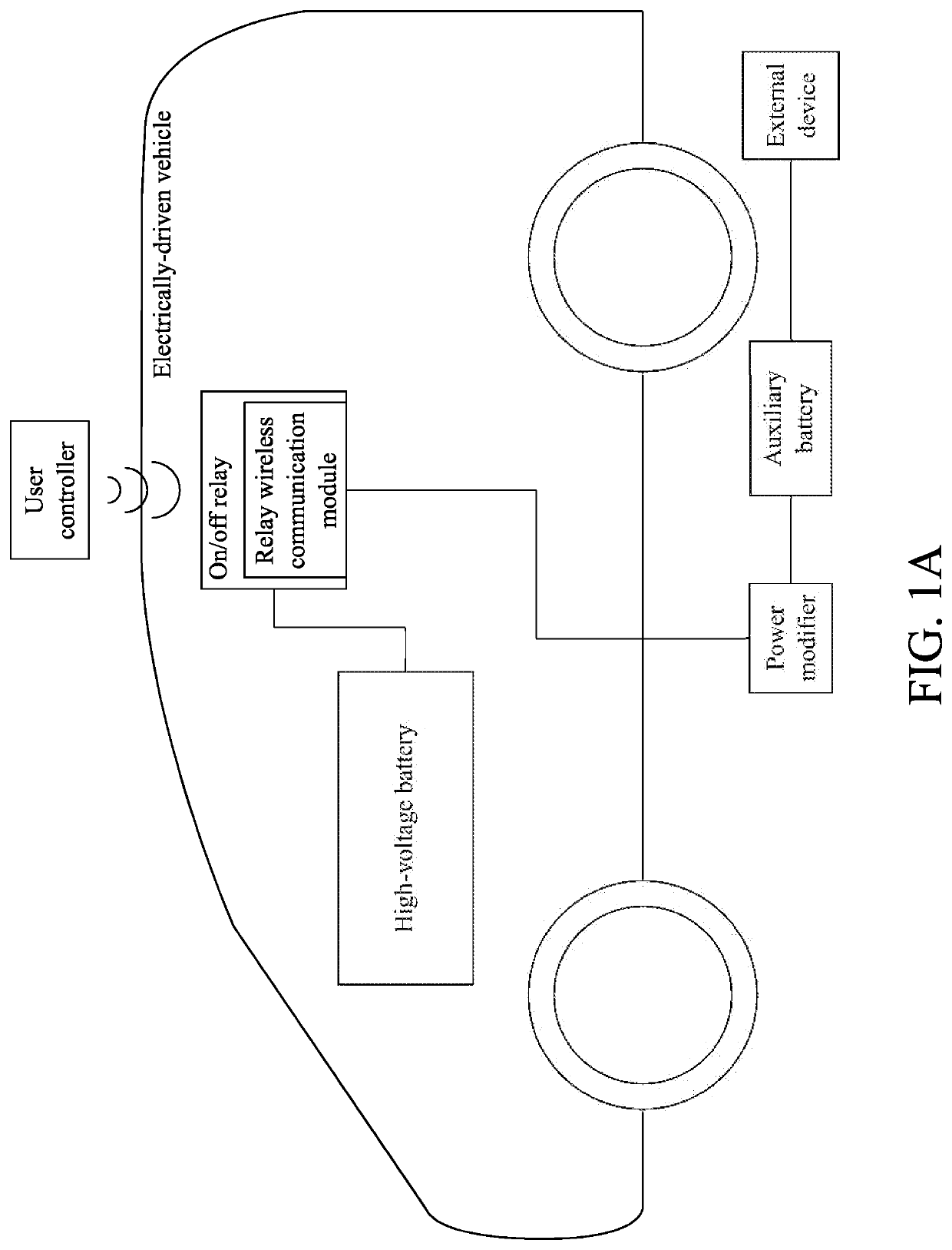
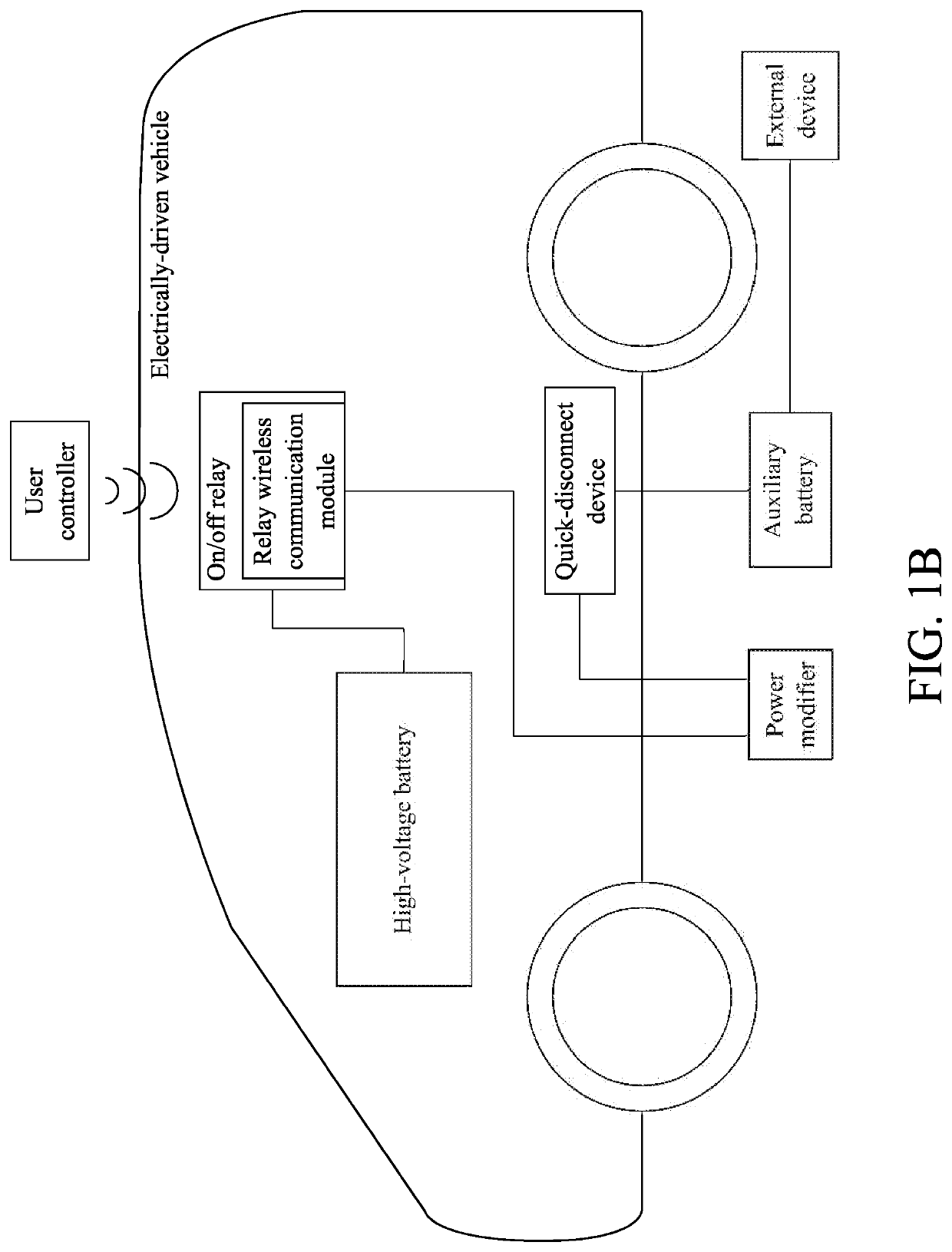
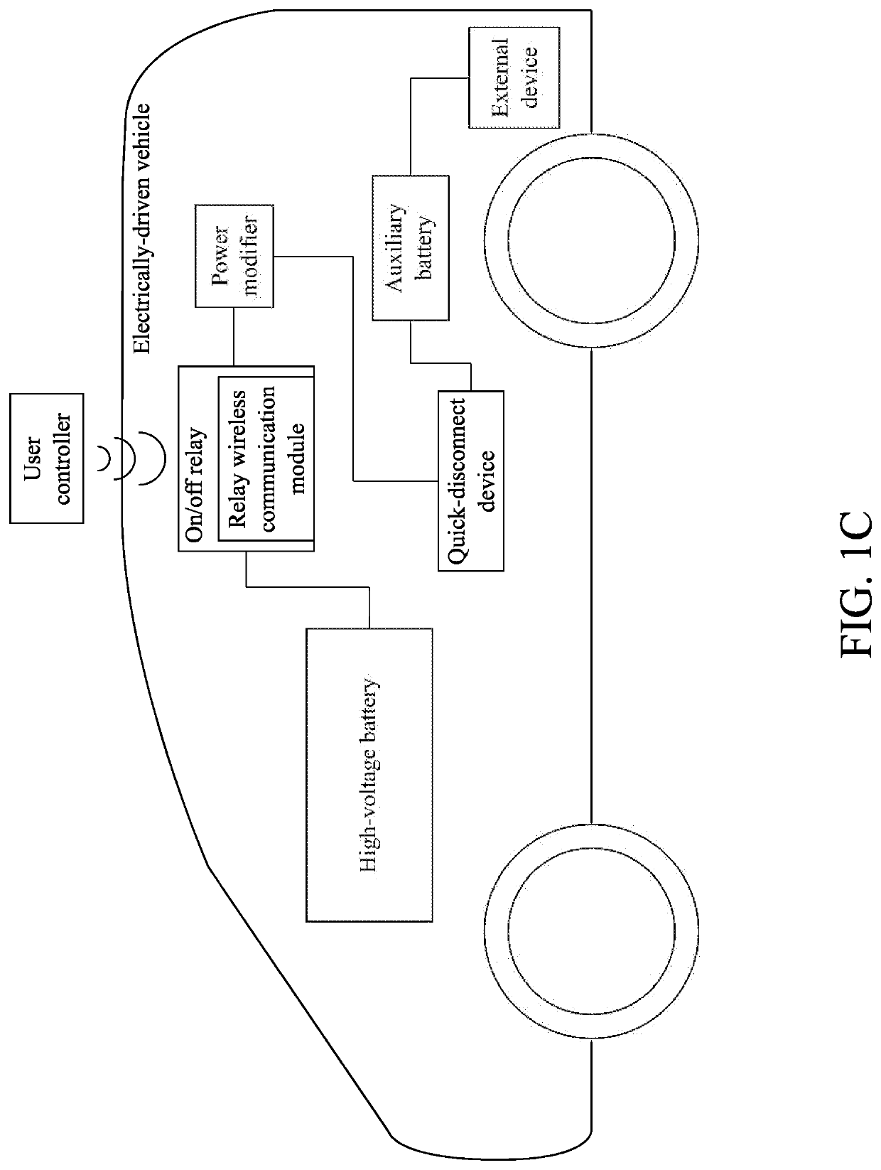
[0037]The present invention is a system and method of powering an external device with a vehicular battery system. The system allows a user to easily draw power from a vehicular battery system in order to power external electrical devices. The power is drawn in a unilateral direction eliminating the need to communicate with a vehicle's onboard electronic control unit (ECU). With reference to FIG. 1A, the system is provided with an electrically-driven vehicle (Step A). The electrically-driven vehicle may be a hybrid vehicle that generates its own electrical power with its hybrid internal combustion engine. Further, the electrically-driven vehicle may be a vehicle with a high-voltage battery source such as, but not limited to, a Tesla type vehicle. The electrically-driven vehicle comprises at least one hig...


PUM


Abstract

A system and a method of powering an external device with a vehicular battery system allow a user to charge electrically-powered devices with the electrical power source of his or her vehicle. The system includes an electrically-driven vehicle which includes a high-voltage battery. The system further includes a power modifier, an auxiliary battery, at least one external device, at least one on / off relay, and a user controller. The power modifier modifies the high-voltage DC drawn from the high-voltage battery to safely charge the auxiliary battery. The auxiliary battery stores electrical power. The external device may be any electrically-powered device. The on / off relay allows a user to turn the system on or off when desired. The user controller is communicably coupled to the on / off relay through a relay wireless communication module. The user controller allows a user to remotely operate the on / off relay and, thus, remotely turn the system on or off.

Description

[0001]The current application is a continuation-in-part (CIP) application of a U.S. non-provisional application Ser. No. 16 / 600,425 filed on Oct. 11, 2019. The U.S. non-provisional application Ser. No. 16 / 600,425 claims a priority to the U.S. Provisional Patent application Ser. No. 62 / 744,542 filed on Oct. 11, 2018.FIELD OF THE INVENTION[0002]The present invention relates generally to a field of electric vehicles. More specifically, the present invention relates to methods and systems to transfer electrical energy generated or stored from an electrically-driven vehicle to an auxiliary battery with a vehicular battery system.BACKGROUND OF THE INVENTION[0003]A hybrid vehicle usually generates a significant amount of electrical energy while operating and / or moving on a highway. Even at a time of braking from a high speed, a significant amount of electrical energy may be generated by the hybrid vehicle that may charge a battery of the hybrid vehicle. The electrical energy generated may ...

Claims


Application Information

Patent Timeline
IPC IPC(8): B60L1/00B60L50/64B60L50/60B60L58/20H02J7/00
CPCB60L1/00B60L50/64H02J2310/48B60L58/20H02J7/0063B60L50/66B60L1/006H02J7/342H02J7/00309Y02T10/70Y02T90/16
Inventor JOHNSON, KEITH
Owner JOHNSON KEITH
Why Eureka
Eureka Blog
Learn More