Method for coating a pipe and pipe

a technology of coating and pipe, applied in the direction of superimposed coating process, liquid fuel feeder, machine/engine, etc., to achieve the effect of cost saving, easy operation and low effor

Pending Publication Date: 2022-01-20
TI AUTOMOTIVE HEIDELBERG
View PDF7 Cites 0 Cited by
  • Summary
  • Abstract
  • Description
  • Claims
  • Application Information

AI Technical Summary

Benefits of technology

[0005]On the one hand, the disclosure is based on the discovery that applying the bonding layer via plasma coating can be done relatively easily and with little effort. The complicated parameter settings known from prior art or practice are eliminated. The method according to the disclosure is also characterized by advantages over the previously known methods when it comes to environmental aspects and health aspects. The bonding layers can be applied very homogeneously, and defects are quasi precluded in the process. The bonding layer can be reproducibly applied with a constant, low layer thickness. The method according to the disclosure or the coating according to the disclosure is further also characterized by relatively low costs.
[0015]The disclosure is based upon the discovery that applying the bonding layer between the metal layer and the outer layer brings with it very special advantages. On the one hand, this plasma coating can be performed very easily and with little effort. The complicated measures in the wet chemical method known from practice can be completely eliminated in the disclosure. In this regard, the environmental and health problems associated with the known measures can also be avoided. Complex parameter settings are completely eliminated in the disclosure. The bonding layer applied with the plasma coating can be applied in a reproducibly homogeneous manner and with a constant layer thickness. These measures are relatively cost effective, and can nonetheless be effectively and precisely implemented.

Problems solved by technology

In addition, the technical problem underlying the disclosure is to indicate a corresponding pipe.

Method used


Image

  • Method for coating a pipe and pipe
  • Method for coating a pipe and pipe

Examples


Embodiment Construction

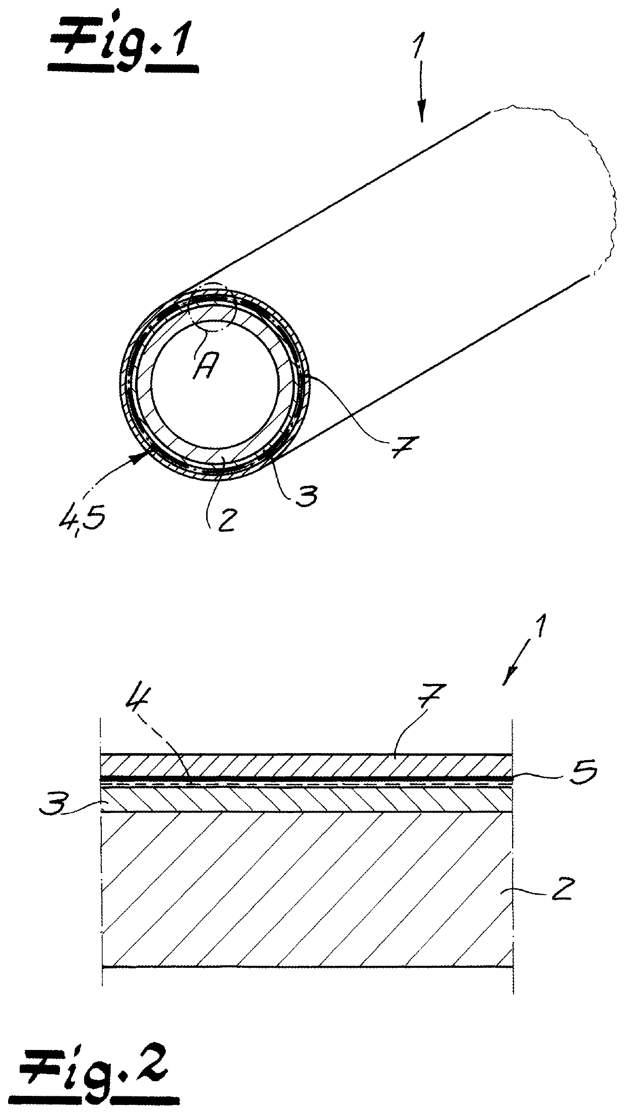
[0020]The figures show a pipe 1, which was coated based on the method according to the disclosure. In the exemplary embodiment, a motor vehicle pipe can preferably be involved, which is preferably used for fuels and / or hydraulic fluids. The pipe 1 has a metallic inner tube 2, which in the exemplary embodiment is preferably designed as a steel tube. This metallic inner tube 2 is provided with a metal layer 3, which in the exemplary embodiment is preferably designed as an aluminum layer. The aluminum layer can have been applied to the metallic inner tube 2 in a hot-dip method. In particular, a metal layer 3 made of Galfan can be applied to the metallic inner tube 2 instead of an aluminum layer.

[0021]In a preferred embodiment and in the exemplary embodiment, a chrome-free intermediate layer 4 is applied to the metal layer 3 or the aluminum layer, and in one embodiment can have a phosphatizing agent.—The layer thickness of the metal layer 3 can measure 50 to 150 μm in the exemplary embo...


PUM

PropertyMeasurementUnit
thicknessaaaaaaaaaa
thicknessaaaaaaaaaa
thicknessaaaaaaaaaa

Abstract

A method for coating a pipe, in particular a motor vehicle pipe, wherein a metallic inner tube is used, and wherein the outer surface of the metallic inner tube is provided with at least one metal layer. A bonding layer is thereupon applied to the metal layer. The pipe is then provided with at least one outer layer. The bonding layer is applied via plasma coating.

Description

RELATED APPLICATIONS[0001]The present disclosure claims priority to European Application 20185920.4 filed on Jul. 15, 2020, the entire contents of each of which are incorporated herein by reference.FIELD[0002]The disclosure relates to a method for coating a pipe, in particular a motor vehicle pipe, preferably for fuels and / or hydraulic fluids, wherein a metallic inner tube is used, wherein the outer surface of the metallic inner tube is provided with at least one metal layer, wherein at least one bonding layer is thereupon applied to the metal layer, and wherein the pipe is thereupon provided with at least one outer layer. The disclosure further relates to a corresponding pipe, preferably for fuels and / or hydraulic fluids.BACKGROUND[0003]Methods of the kind described above are known in practice in various embodiments. As a rule, the bonding layer is here applied within the framework of wet chemical methods. The bonding layer is here used dissolved in a solvent. In this respect, the ...

Claims


Application Information

Patent Timeline
Patent Type & Authority Applications(United States)
IPC IPC(8): C23C28/00H05H1/24C23C2/04
CPCC23C28/32C23C2/04H05H1/24C23C28/00C23C2/38C23C2/06C22C18/04C23C2/12C23C14/22C23C16/44F02M37/0017C23C4/08C23C28/021C23C28/023C23C4/134C23C4/14C23C4/16B21C37/123C23C16/513C23C28/34C23C2/26C23C22/07B05D7/222F16L9/147
Inventor TSCHACHTSCHAL, ALEXANDERSINN, CHRISTIAN
Owner TI AUTOMOTIVE HEIDELBERG
Why Eureka
Try Eureka