
Wireless communication system

Pending Publication Date: 2022-01-20
SAFRAN ELECTRONICS & DEFENSE
View PDF2 Cites 0 Cited by
  • Summary
  • Abstract
  • Description
  • Claims
  • Application Information

AI Technical Summary

Benefits of technology

The invention is a central communication unit that reduces the number of frames needed for wireless communication, leading to improved efficiency and reduced power consumption. It also allows for the introduction of redundancy in the exchanges, enhancing the availability of the wireless communication system. Furthermore, it offers easy upgradability, allowing for easy addition of new subscriber communication units.

Problems solved by technology

Several protocols are known that enable half-duplex communication to be performed, however none of those known protocols is entirely satisfactory.
The number of frames exchanged during each communication cycle is large, being equal to 3.N, such that exchanges in that protocol are not very efficient.
A consequence of such poor efficiency is a relatively high level of consumption of electricity by the wireless communication system 1 (since numerous exchanges are necessary in order to communicate a given amount of data).
Furthermore, that wireless communication system 1 presents availability that is relatively low.

Method used


Image

  • Wireless communication system
  • Wireless communication system
  • Wireless communication system

Examples


Embodiment Construction

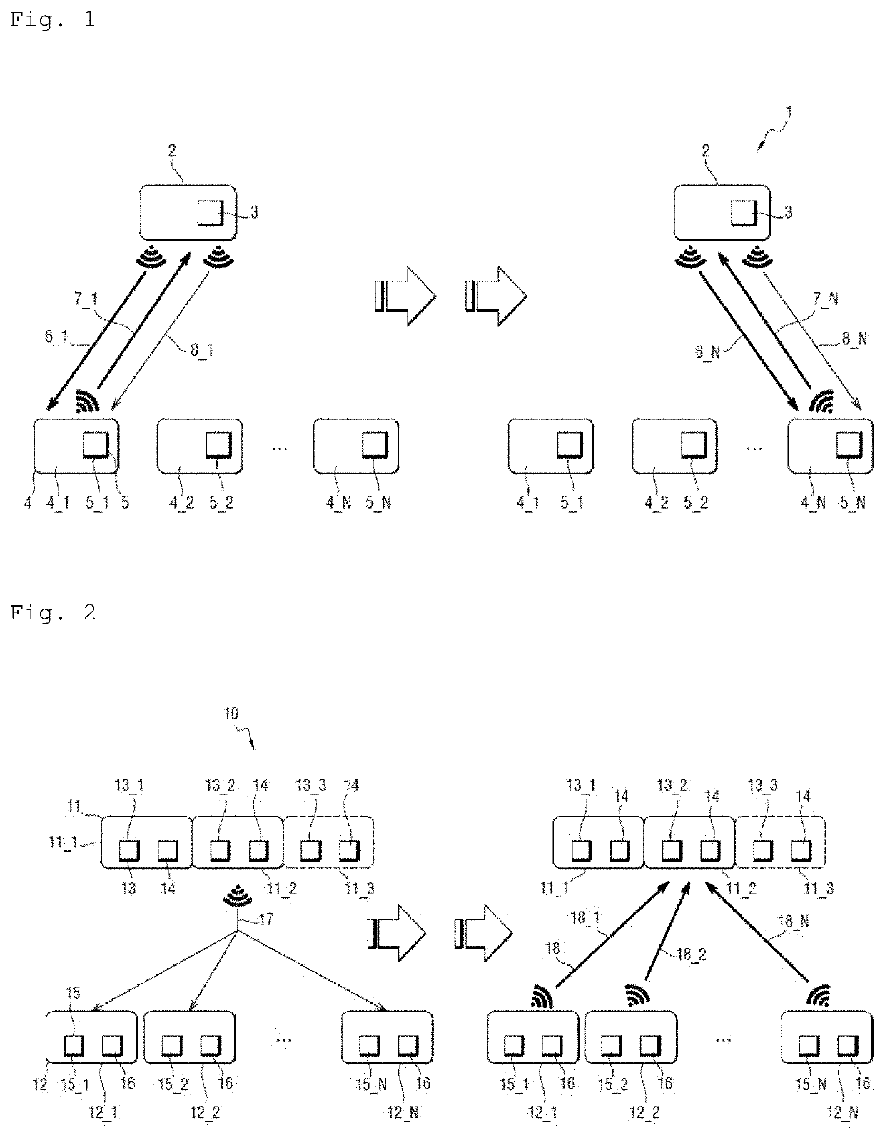
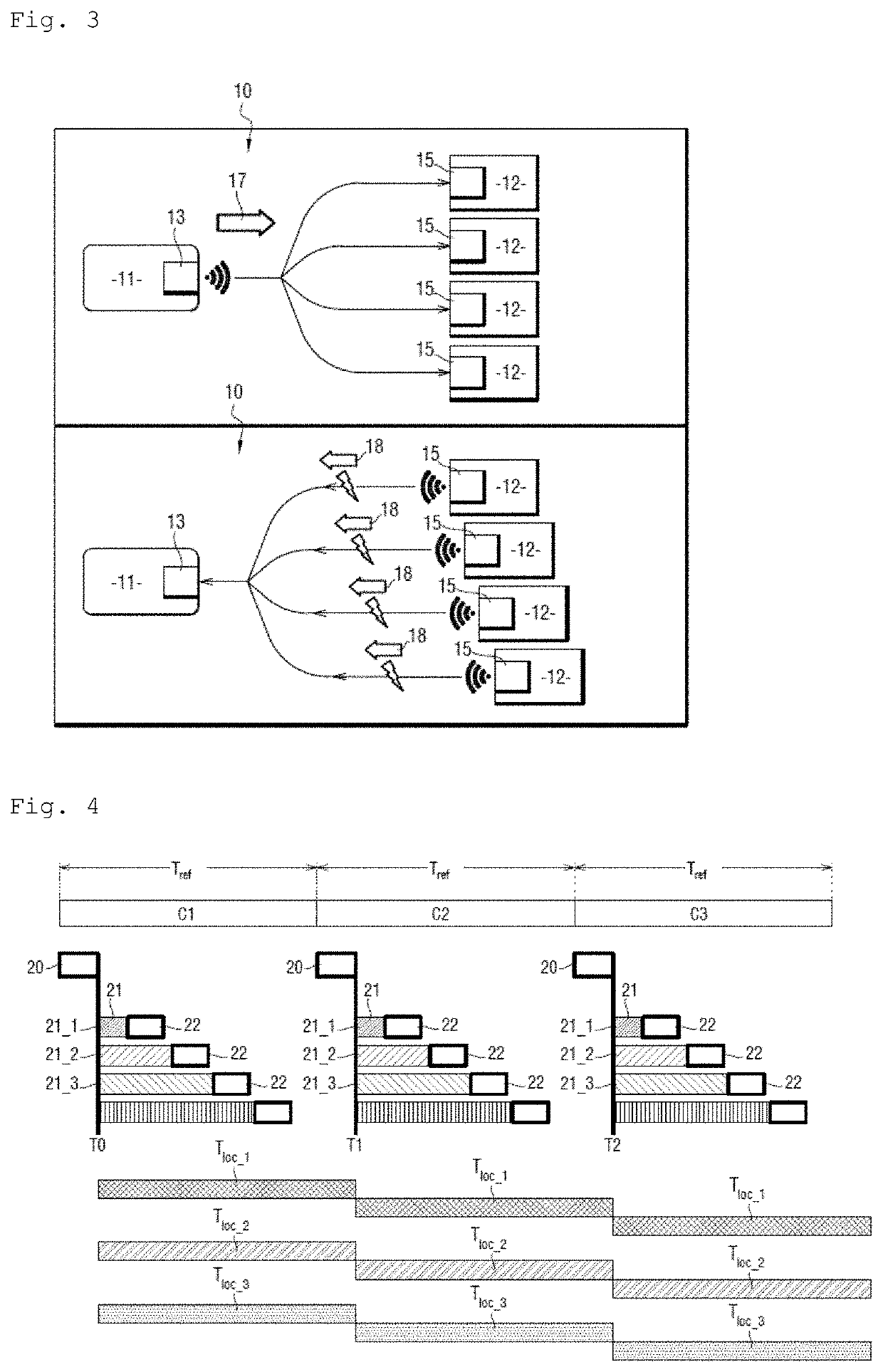
[0073]With reference to FIG. 2, the wireless communication system 10 of the invention is embedded in an aircraft and comprises one or more central pieces of equipment 11 (11_1, 11_2, 11_3) and a plurality of remote pieces of equipment 12, specifically N remote pieces equipment 12 (12_1, 12_2, . . . , 12_N). In this example, the pieces of central equipment 11 are data concentrators (in the general sense) and the remote pieces of equipment 12 are sensors. The data concentrators 11 and the sensors 12 may be located inside or outside the fuselage, e.g. in the cockpit, on the wings, on or in the engines, the landing gear, etc.

[0074]Each data concentrator 11 includes a central communication unit 13 and a processor module 14 that produces and acquires the frames that are exchanged by the central communication unit 13. The processor module 14 includes a processor component that, by way of example, may be a microcontroller, a processor, or indeed a programmable logic circuit such as a field ...


PUM


Abstract

A central communication unit (13), comprising:transmitter means arranged to transmit a single global downlink frame (17) addressed to all of the subscriber communication units, the global downlink frame comprising a plurality of data packets, each addressed to a respective one of the subscriber communication units, the global downlink frame supplying a common reference time so that, after receiving the global downlink frame (17), each subscriber communication unit can start transmitting an uplink frame (18) at the end of a waiting interval starting at the common reference time and having a duration equal to a respective waiting duration that is associated with said subscriber communication unit; andreceiver means arranged to receive in succession the uplink frames (18) transmitted by each of the subscriber communication units.

Description

[0001]The invention relates to the field of wireless communication systems, and it relates in particular to wireless communication systems incorporated in aircraft.BACKGROUND OF THE INVENTION[0002]Proposals are presently being made to replace the electric cables that convey data in modern aircraft with wireless communication. This is generally referred to as “wireless avionics intra-communication” (WAIC).[0003]Several protocols are known that enable half-duplex communication to be performed, however none of those known protocols is entirely satisfactory.[0004]With reference to FIG. 1, there follows a description of the implementation of a known protocol in a wireless communication system 1.[0005]The wireless communication system 1 includes a central piece of equipment 2 incorporating a central communication unit 3, together with N remote pieces of equipment 4 (4_1, 4_2, . . . , 4_N), each of which incorporates a respective subscriber communication unit 5. The central communication u...

Claims


Application Information

Patent Timeline
IPC IPC(8): H04W4/06H04L1/16H04W24/04
CPCH04W4/06H04W24/04H04L1/1607H04W74/006H04W72/0446H04W72/23
Inventor TOILLON, PATRICEJEANDON, THIEBAULTMOREAU, CÉDRIC
Owner SAFRAN ELECTRONICS & DEFENSE
Features
  • Generate Ideas
  • Intellectual Property
  • Life Sciences
  • Materials
  • Tech Scout
  • Unparalleled Data Quality
  • Higher Quality Content
  • 60% Fewer Hallucinations
Learn More