Distribution pump arrangement for a hydraulic distribution system having changing flowing direction

a technology of hydraulic distribution system and distribution pump, which is applied in the direction of fluid pressure control, heating types, instruments, etc., to achieve the effect of reducing local pressure differen

Pending Publication Date: 2022-01-27
E ON SVERIGE
View PDF0 Cites 0 Cited by
  • Summary
  • Abstract
  • Description
  • Claims
  • Application Information

AI Technical Summary

Benefits of technology

[0007]The controller is configured to: while Δp<a threshold value, set the distribution pump arrangement in a flowing mode, wherein the first distribution pump is set to be inactive, and wherein the hot conduit control valve is set to be open, thereby allow a flow of heat transfer liquid of the hot conduit through the hot conduit control valve; and while Δp the threshold value and pcold>phot, set the distribution pump arrangement in a hot conduit pumping mode, wherein the hot conduit control valve is set to be closed, thereby stop a flow of heat transfer liquid of the hot conduit through the hot conduit control valve, and wherein the first distribution pump is set to be active, thereby reduce the local pressure difference.
[0008]The distribution pump arrangement allows for design freedom in designing a bi-directional hydraulic distribution grid and the assemblies for extracting heat from and / or depositing heat in the bi-directional hydraulic distribution grid. This since a to high local pressure differences may be handled by the distribution pump arrangement.
[0009]According to an embodiment the distribution pump arrangement may further comprise: a cold conduit control valve in the cold conduit; and a second distribution pump having an outlet connected to the cold conduit at a first side of the cold conduit control valve, and an inlet connected to the cold conduit at a second side, opposite the first side, of the cold conduit control valve. The pressure difference determining device may be arranged beyond the second side of the cold conduit control valve. While the distribution pump arrangement is set in the flowing mode the second distribution pump may be set to be inactive. While the distribution pump arrangement is set in the flowing mode the cold conduit control valve may be set to be open, thereby allow a flow of heat transfer liquid of the cold conduit through the cold conduit control valve. While the distribution pump arrangement is set in the hot conduit pumping mode, the cold conduit control valve may be set to be closed, thereby stop a flow of heat transfer liquid of the cold conduit through the cold conduit control valve. While the distribution pump arrangement is set in the hot conduit pumping mode, the second distribution pump may be set to be active, thereby reduce the local pressure difference.

Problems solved by technology

There are design challenges determining type of pumps and valves to be used in a system comprising the bi-directional hydraulic distribution grid and the assemblies for extracting heat from and / or depositing heat in the bi-directional hydraulic distribution grid.

Method used


Image

  • Distribution pump arrangement for a hydraulic distribution system having changing flowing direction
  • Distribution pump arrangement for a hydraulic distribution system having changing flowing direction
  • Distribution pump arrangement for a hydraulic distribution system having changing flowing direction

Examples


first embodiment

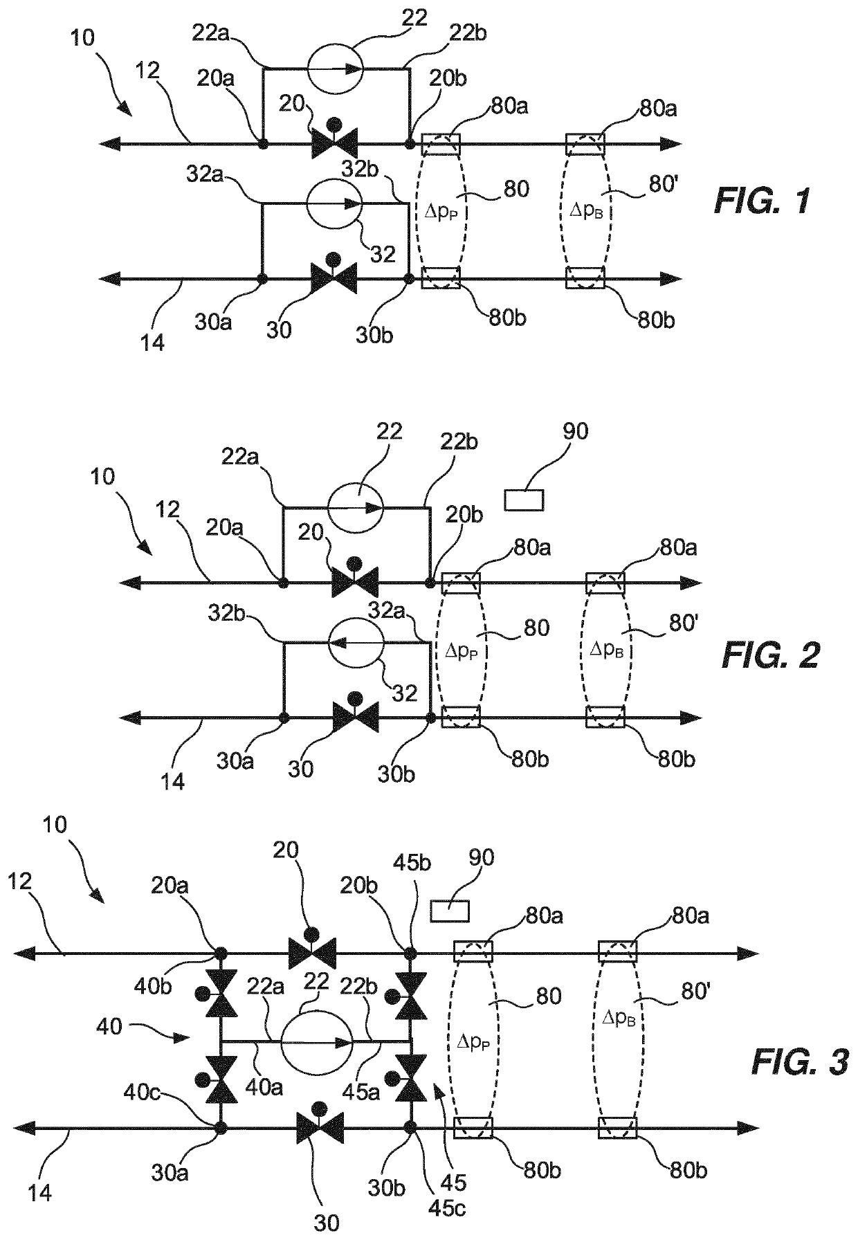
[0038]In connection with FIG. 1 a first embodiment of the distribution pump arrangement will be discussed. According to this first embodiment the distribution pump arrangement comprises a hot conduit control valve 20, a hot conduit distribution pump 22, a pressure difference determining device 80, 80′, and a controller 90. This first embodiment of the distribution pump arrangement is configured to reduce a local pressure difference between heat transfer fluid of the hot and cold conduits 12, 14 when the local pressure of heat transfer fluid in the cold conduit 14 is higher than the local pressure of heat transfer fluid in the hot conduit 12.

[0039]The hot conduit control valve 20 is arranged in the hot conduit 12. The hot conduit control valve 20 is controllable by the controller 90. The hot conduit control valve 20 may be set in either an open state or in a closed state. In the open state, heat transfer liquid of the hot conduit 12 is allowed to flow through the hot conduit control ...

second embodiment

[0044]In connection with FIG. 2 a second embodiment of the distribution pump arrangement will be discussed. In addition to the first embodiment of the distribution pump arrangement this second embodiment further comprises a cold conduit control valve 30 and a cold conduit distribution pump 32. Just as the first embodiment of the distribution pump arrangement this second embodiment is configured to reduce a local pressure difference between heat transfer fluid of the hot and cold conduits 12, 14 when the local pressure of heat transfer fluid in the cold conduit 14 is higher than the local pressure of heat transfer fluid in the hot conduit 12.

[0045]The cold conduit control valve 30 is arranged in the cold conduit 14. The cold conduit control valve 30 is controllable by the controller 90. The cold conduit control valve 30 may be set in either an open state or in a closed state. In the open state, heat transfer liquid of the cold conduit 14 is allowed to flow through the cold conduit co...

third embodiment

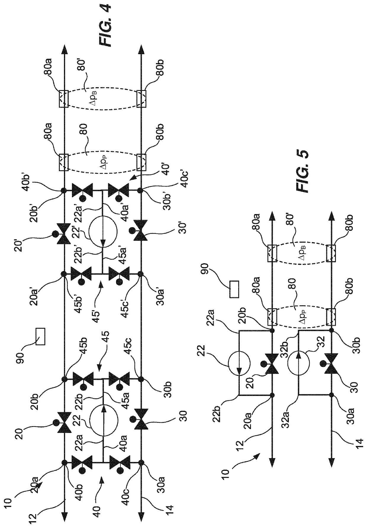
[0050]In connection with FIG. 3 a third embodiment of the distribution pump arrangement will be discussed. In addition to the first embodiment of the distribution pump arrangement this third embodiment further comprises a cold conduit control valve 30, a first pump inlet valve assembly 40, and a first pump outlet valve assembly 45. Just as the first embodiment of the distribution pump arrangement this third embodiment is configured to reduce a local pressure difference between heat transfer fluid of the hot and cold conduits 12, 14 when the local pressure of heat transfer fluid in the cold conduit 14 is higher than the local pressure of heat transfer fluid in the hot conduit 12. However, in addition to this, this third embodiment may also be configured to reduce a local pressure difference between heat transfer fluid of the hot and cold conduits 12, 14 when the local pressure of heat transfer fluid in the hot conduit 12 is higher than the local pressure of heat transfer fluid in the...


PUM


Abstract

The present invention relates to a distribution pump arrangement for a bi-directional hydraulic distribution grid (10). The distribution pump arrangement comprising: a hot conduit control valve (20) in a hot conduit (12); a first distribution pump (22) having an inlet (22a) connected to the hot conduit (12) at a first side (20a) of the hot conduit control valve, and an outlet (22b) connected to the hot conduit (12) at a second side (20b), opposite the first side (20a), of the hot conduit control valve (20); a pressure difference determining device (80, 80′) arranged beyond the second side of the hot conduit control valve (20) and configured to determine a local pressure difference, Δp, between a local pressure, phot, of heat transfer liquid in the hot conduit (12) and a local pressure, pcold, of heat transfer liquid in the cold conduit (14); and a controller (90) configured to: while Δp<a threshold value, set the distribution pump arrangement in a flowing mode, wherein: the first distribution pump (22) is set to be inactive, and the hot conduit control valve (20) is set to be open, while Δp≥the threshold value and pcold>phot, set the distribution pump arrangement in a hot conduit pumping mode, wherein: the hot conduit control valve (20) is set to be closed, and the first distribution pump (22) is set to be active, thereby reduce the local pressure difference.

Description

TECHNICAL FIELD[0001]The present invention relates to a distribution pump arrangement for a bi-directional hydraulic distribution grid.BACKGROUND[0002]In recent years' bi-directional hydraulic distribution grids configured to distribute thermal energy to and from buildings in a district has been realized. An example of such a bi-directional hydraulic distribution grid has been presented by the applicant under the trademark Ectogrid™. The Ectogrid™ bi-directional hydraulic distribution grid is further described in WO 2017 / 076868. Such a bi-directional hydraulic distribution grid comprises a hot conduit configured to bi-directionally allow heat transfer liquid of a first temperature to flow therethrough and a cold conduit configured to bi-directionally allow heat transfer liquid of a second temperature to flow therethrough. The second temperature is lower than the first temperature. Assemblies for extracting heat from and / or depositing heat in the bi-directional hydraulic distribution...

Claims


Application Information

Patent Timeline
Patent Type & Authority Applications(United States)
IPC IPC(8): F24D19/10G05D16/20F24D3/02
CPCF24D19/1006G05D16/2073F24D2220/046F24D3/02F24D2220/02G05D16/208F24D10/00G05D16/028Y02B30/17
Inventor ROSÉN, PERSKOGSTRÖM, JACOBROSENQVIST, FREDRIKLINDOFF, BENGT
Owner E ON SVERIGE
Why Eureka
Try Eureka