Ducted fan device

a technology of ducted fan and fan body, which is applied in the direction of efficient propulsion technologies, machines/engines, liquid fuel engines, etc., can solve the problems of reducing the weight of ducted fan devices, and achieve the effect of enhancing the retention capability at the time of fbo

Active Publication Date: 2022-02-03
HONDA MOTOR CO LTD
View PDF4 Cites 0 Cited by
  • Summary
  • Abstract
  • Description
  • Claims
  • Application Information

AI Technical Summary

Benefits of technology

[0026]In the ducted fan device according to the present invention, the containment capability at the time of FBO is enhanced without hindering the weight reduction.

Problems solved by technology

This hinders the weight reduction of the ducted fan device.

Method used


Image

  • Ducted fan device
  • Ducted fan device
  • Ducted fan device

Examples


first embodiment

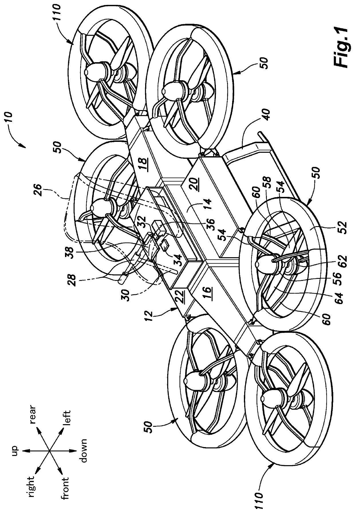
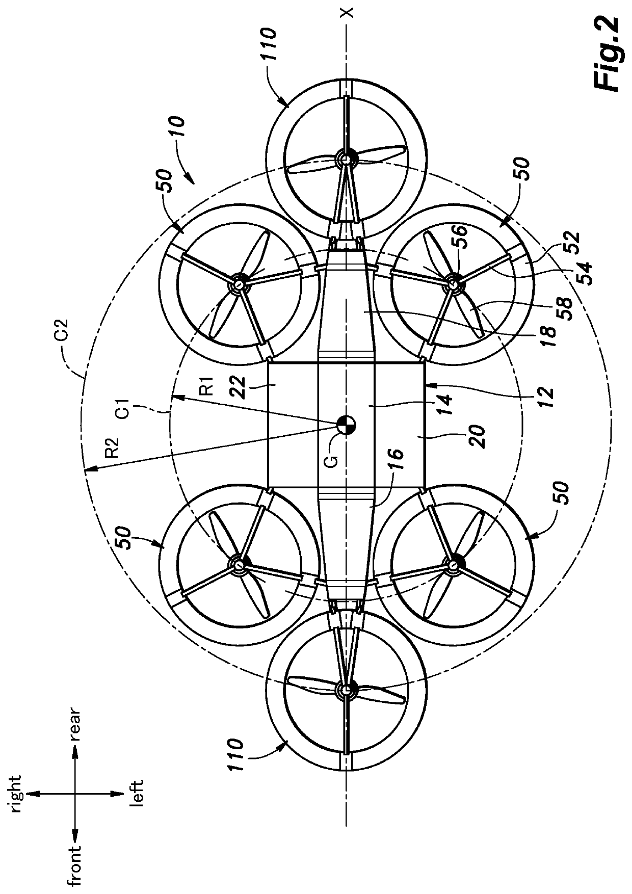
[0045]As shown in FIG. 1, each first ducted fan device 50 of the first embodiment includes counter-rotating blades arranged concentrically one above the other, and includes an annular fan shroud (duct) 52 attached to the machine body 12 and having an open upper end and an open lower end, an upper electric motor 56 disposed at the center of the fan shroud 52 by multiple upper arms 54, an upper fan blade (rotating blade) 58 fitted to a rotary shaft of the upper electric motor 56 to face downward and driven to rotate by the upper electric motor 56, a lower electric motor 62 disposed coaxially with the upper electric motor 56 by multiple lower arms 60, and a lower fan blade 64 fitted to a rotary shaft of the lower electric motor 62 to face upward and driven to rotate by the lower electric motor 62. The upper fan blade 58 and the lower fan blade 64 are coaxially arranged to vertically oppose each other with a space therebetween and rotate in mutually opposite directions. The combination ...

second embodiment

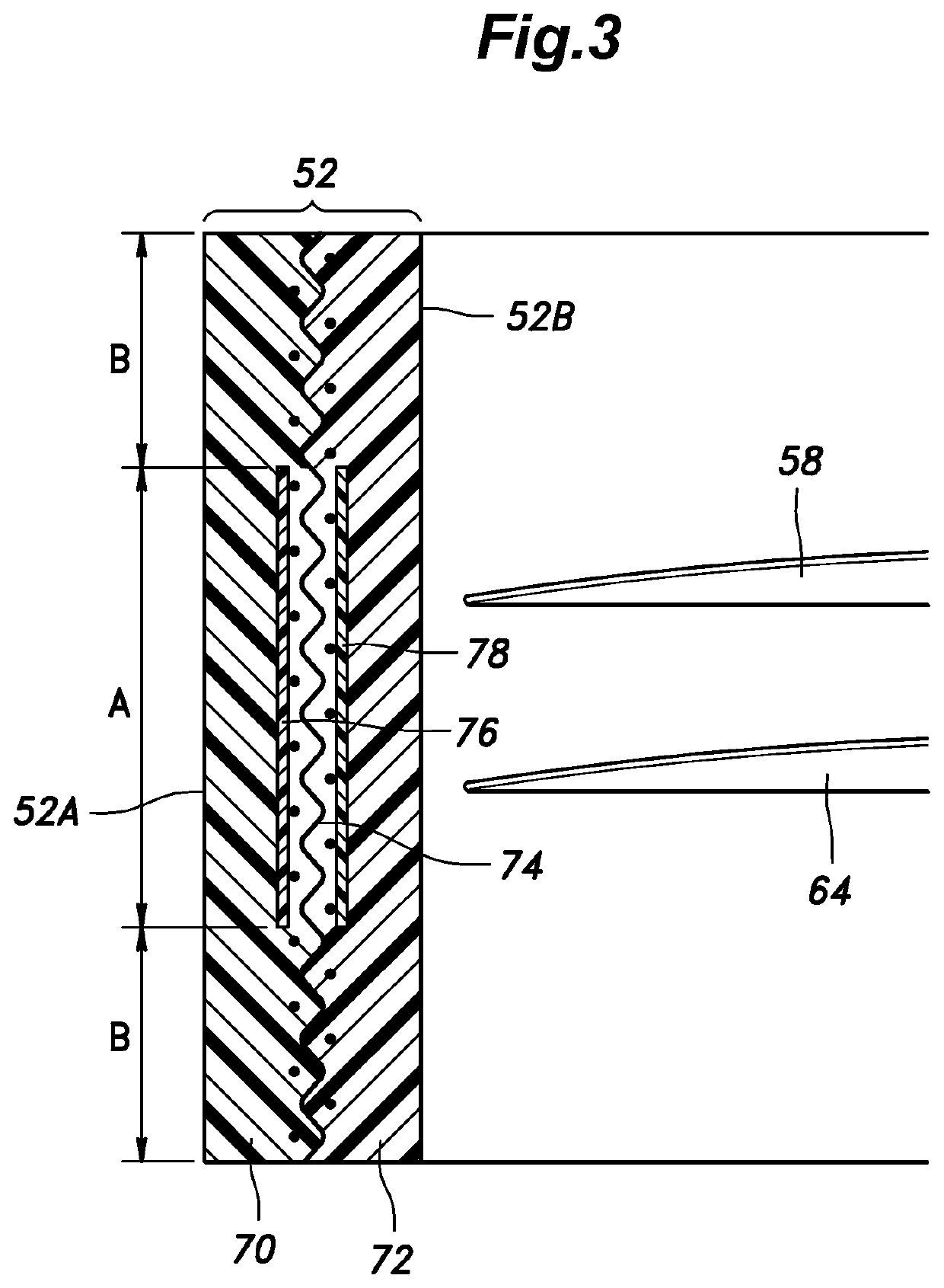
[0057]The first ducted fan device 50 is described with reference to FIG. 6. Note that in FIG. 6, parts corresponding to those in FIG. 3 are denoted by the same reference signs as in FIG. 3 and the description thereof will be omitted.

[0058]In the second embodiment, the inner resin layer 72 in the first embodiment is omitted, and the fiber layer 74 is exposed on the inner circumferential surface of the fan shroud 52. Namely, the resin layer (the outer resin layer 70) is provided only on the radially outer surface of the fan shroud 52.

[0059]In the second embodiment, the fan blade fragments at the time of FBO are stuck directly in the fiber layer 74 in the opposing section A and are captured by the fiber layer 74, and due to the minimum laminated structure, the containment capability at the time of FBO is enhanced without hindering the weight reduction of the first ducted fan device 50.

[0060]In the second embodiment also, the fiber layer 74 in the opposing section A is not impregnated ...

third embodiment

[0061]The first ducted fan device 50 is described with reference to FIG. 7. Note that in FIG. 7, parts corresponding to those in FIG. 3 are denoted by the same reference signs as in FIG. 3 and the description thereof will be omitted.

[0062]In the third embodiment, the fan shroud 52 has a multilayer structure including an outer resin layer 80 constituting the outer circumferential surface 52A of the fan shroud 52, an inner resin layer 82 constituting the inner circumferential surface 52B of the fan shroud 52, an intermediate resin layer 84 disposed between the outer resin layer 80 and the inner resin layer 82, a fiber layer 86 sandwiched by the outer resin layer 80 and the intermediate resin layer 84, and a fiber layer 88 sandwiched by the inner resin layer 82 and the intermediate resin layer 84.

[0063]In the opposing section A, resin insulation sheets 90, 92, 94, 96 are disposed between the fiber layer 86 and the outer resin layer 70, between the fiber layer 86 and the intermediate r...


PUM


Abstract

To enhance the containment capability of a ducted fan device at the time of FBO without hindering the weight reduction thereof, in a ducted fan device including a fan shroud (52) having an annular shape in plan view and an electric fan disposed at a center of the fan shroud (52) and having a fan blade (58, 64), the fan shroud (52) has a multilayer structure including a fiber layer (74) and a resin layer (70, 72), and has an opposing section (A) including a part that opposes a tip of the fan blade (58, 64) and a non-opposing section (B) that does not oppose the tips of the fan blade (58, 64), the opposing section and the non-opposing section being arranged in an axial direction, wherein in the non-opposing section (B), the fiber layer (74) is impregnated with part of resin forming the resin layer (70, 72), and in the opposing section (A), the fiber layer (74) is not impregnated with the resin forming the resin layer (70, 72).

Description

TECHNICAL FIELD[0001]The present invention relates to a ducted fan device, and more specifically relates to a ducted fan device having a containment function at the time of FBO (Fan Blade Out).BACKGROUND ART[0002]As a ducted fan device having a containment function at the time of FBO, in which fan blade fragments generated by fracture of a fan blade during fan rotation are thrown in the centrifugal direction, there is known a ducted fan device having a cylindrical fan case that is composed of resin-impregnated composite material containing mutually parallel oriented fibers in a matrix resin and accommodates a rotating fan blade therein, wherein the fiber orientation is set at an angle intersecting a projection line obtained by projecting the tip of the fan blade onto the inner circumferential surface of the fan case (an angle in a range of 90 degrees±30 degrees), so that the impact when the tip of the fan blade thrown at the time of FBO collides with the inner circumferential surfac...

Claims


Application Information

Patent Timeline
Patent Type & Authority Applications(United States)
IPC IPC(8): F04D29/54F04D25/06B64C27/20B64D27/24
CPCF04D29/545B64D27/24B64C27/20F04D25/06B64C11/001F04D29/526F01D21/045F04D19/00F04D29/023F05D2300/6031F05D2300/603Y02T50/40Y02T50/60
Inventor ISHITSUKA, YUJI
Owner HONDA MOTOR CO LTD
Why Eureka
Try Eureka