V2x vehicle-mounted device and v2x relay
a vehicle-mounted device and relay technology, applied in vehicle components, location information based services, instruments, etc., can solve the problems of not being able to notify drivers, radio waves may not reach another vehicle requiring vehicle information, etc., to reduce unnecessary transmission and prevent the increase of communication traffic of a v2x communication system
- Summary
- Abstract
- Description
- Claims
- Application Information
AI Technical Summary
Benefits of technology
Problems solved by technology
Method used
Image
Examples
embodiment 1
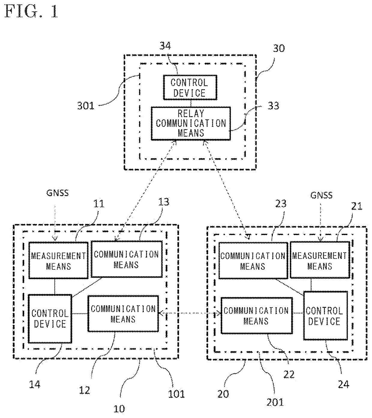
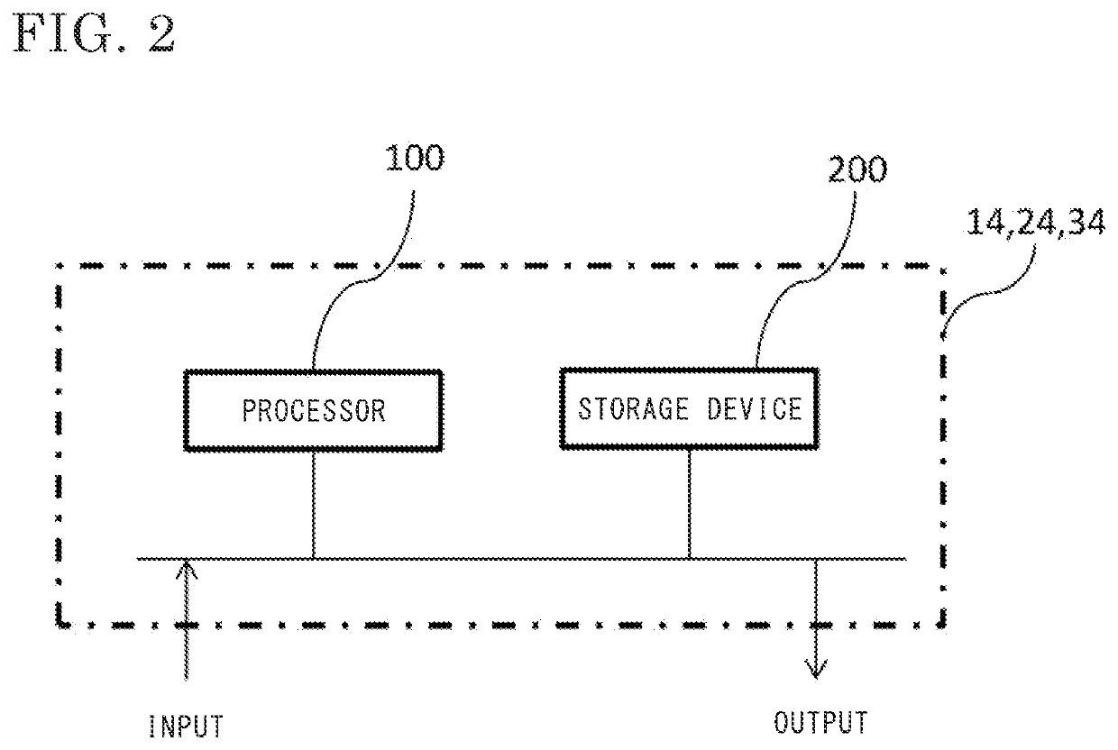
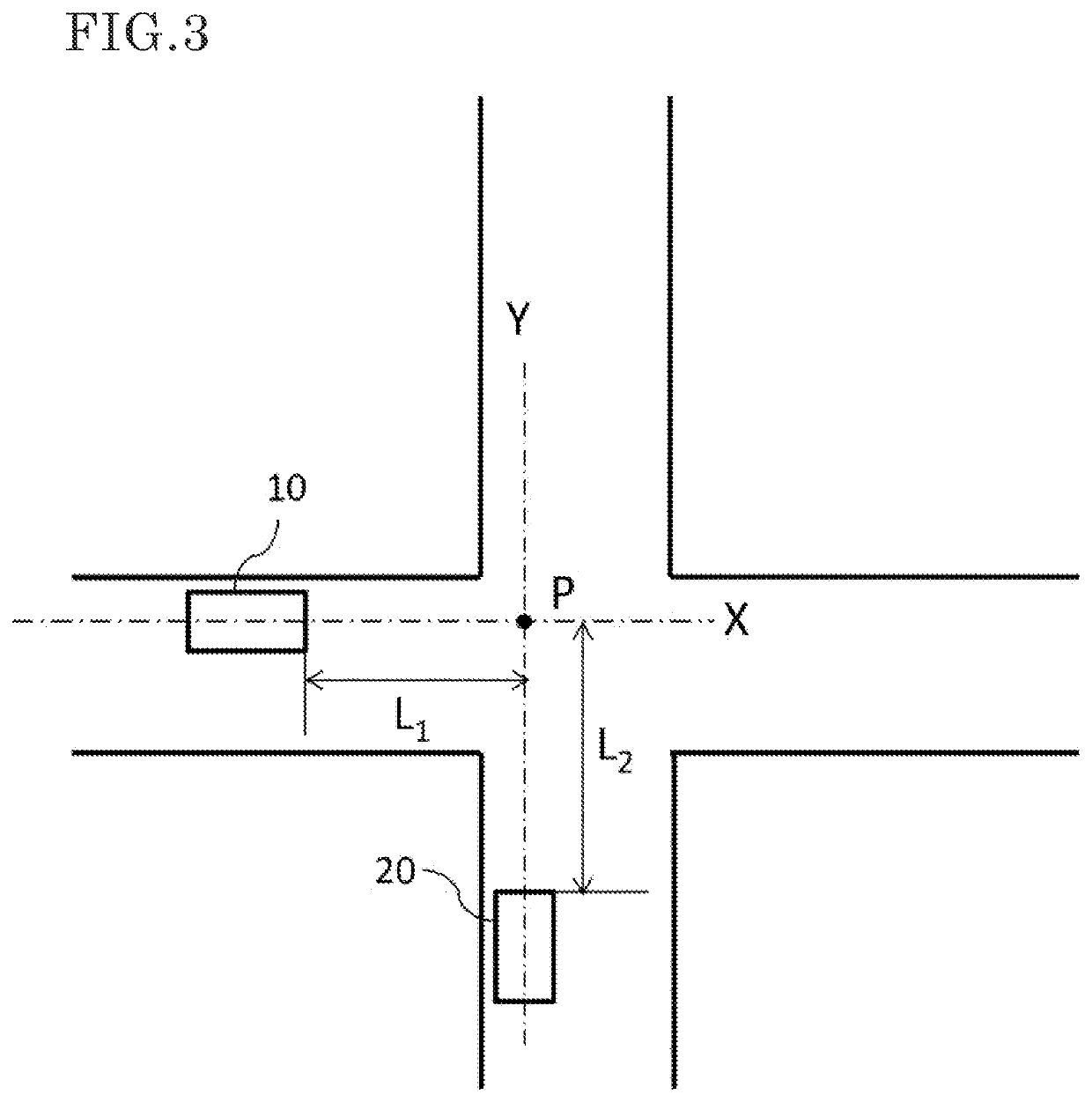
[0028]FIG. 1 is a diagram showing an overall configuration of a V2X communication system according to embodiment 1, FIG. 2 is a diagram showing a hardware configuration of each of control devices mounted in V2X vehicle-mounted devices 101 and 201 in the V2X communication system in FIG. 1, FIG. 3 is a diagram showing a positional relationship between vehicles when the V2X communication system is applied to an intersection collision prevention warning system, and FIG. 4 is a flowchart for illustrating operations of the V2X vehicle-mounted devices 101 and 201 and a V2X relay 301, using the intersection collision prevention warning system as an example.
[0029]The V2X communication system according to embodiment 1 will be described with reference to FIG. 1. In embodiment 1, the V2X communication system is used in an intersection collision prevention warning system described below. In addition to the control devices 14 and 24 described above, measurement means 11 and 21, and communication ...
embodiment 2
[0051]In embodiment 1, whether or not the range of the traveling orientation or the position of the host vehicle is included in the direct transmission difficulty area D indicated in the list of direct transmission difficulty areas received from the base station 30 is determined in the transmission necessity determination processing performed by the control device 14 of the vehicle 10. However, this determination may be performed by the V2X relay 301 of the base station 30. Here, the vehicle information and the list of direct transmission difficulty areas are the same data as those in embodiment 1.
[0052]FIG. 10 is a time-series chart in the case where the control device 34 in the V2X relay 301 of the base station 30 performs determination processing for determining the necessity of transmission of the vehicle information when the vehicle 10 has entered the direct transmission difficulty area D in which radio waves transmitted at the time of direct communication of the vehicle inform...
embodiment 3
[0057]In embodiments 1 and 2, the inhibition of transmission when relaying is unnecessary is performed by using the list of direct transmission difficulty areas. Meanwhile, a list of direct reception difficulty areas may be held instead of the list of direct transmission difficulty areas.
[0058]Hereinafter, the list of direct reception difficulty areas will be described with reference to FIG. 11 to FIG. 13. FIG. 11 shows an example of reception difficulty areas. An area (hereinafter, referred to as a direct reception difficulty area) F is present in which radio waves transmitted from the vehicle 20 when simultaneous transmission is performed from the vehicle 20 through direct transmission by the communication means 22 do not reach the vehicle 10 due to blocking of the radio waves by the building 50 located between the vehicles.
[0059]In the same manner as the direct transmission difficulty areas shown in FIG. 5 and FIG. 7, the direct reception difficulty area F is represented as a rec...
PUM
 Abstract
Description
Claims
Application Information
 - R&D
- Intellectual Property
- Life Sciences
- Materials
- Tech Scout
- Unparalleled Data Quality
- Higher Quality Content
- 60% Fewer Hallucinations
Browse by: Latest US Patents, China's latest patents, Technical Efficacy Thesaurus, Application Domain, Technology Topic, Popular Technical Reports.
© 2025 PatSnap. All rights reserved.Legal|Privacy policy|Modern Slavery Act Transparency Statement|Sitemap|About US| Contact US: help@patsnap.com


