Ethernet plug connector for a motor vehicle and plug connector assembly including an ethernet plug connector

a technology for ethernet plug connectors and motor vehicles, which is applied in the directions of coupling device connections, transportation and packaging, and coupling device details, etc. it can solve the problems of wide construction, insufficient stability of ethernet plug connectors, and inability to meet safety requirements in sufficient degree of conventional rj-45 ethernet plug connectors, etc., to achieve cost-effective manufacturing and easy replacemen

Pending Publication Date: 2022-02-17
ROBERT BOSCH GMBH
View PDF0 Cites 1 Cited by
  • Summary
  • Abstract
  • Description
  • Claims
  • Application Information

AI Technical Summary

Benefits of technology

[0042]One refinement of the present invention provides that the mating plug connector is designed in the form of a standard interface, the standard interface in particular being a BOSCH micro-flex interface, which is in particular designed in two rows or four rows. A plug connector assembly which is particularly easily replaceable and thus may be manufactured cost-effectively is thus advantageously provided.

Problems solved by technology

It has been shown that conventional RJ-45 Ethernet plug connectors are not able to meet these safety demands to a sufficient extent.
However, because of their geometry with respect to the mating plug connector, and also because of the insulation-displacement connection of the plug connector housing to the lines typically used in RJ-45 plug connectors they are not sufficiently stable against loose contacts and, for example, against strong vibration loads.
Moreover, they have quite a wide construction, require quite rigid cables having 8 lines, and are also not sufficiently shielded.
They are therefore basically not suitable for use in motor vehicles.
If a contact is damaged, it may be replaced easily.
If the plug connector housing is damaged, it may also be replaced easily, in that the contacts are simply removed from the (contact) chambers and inserted into a new plug connector housing.
This may be pushed through the plug connector housing, for example, transversely to the plug-in direction, and may engage behind an undercut of the contact element, so that a displacement of the contact element against the plug-in direction, thus out of the contact chamber, is no longer possible.

Method used


Image

  • Ethernet plug connector for a motor vehicle  and plug connector assembly including an ethernet plug connector
  • Ethernet plug connector for a motor vehicle  and plug connector assembly including an ethernet plug connector
  • Ethernet plug connector for a motor vehicle  and plug connector assembly including an ethernet plug connector

Examples


Embodiment Construction

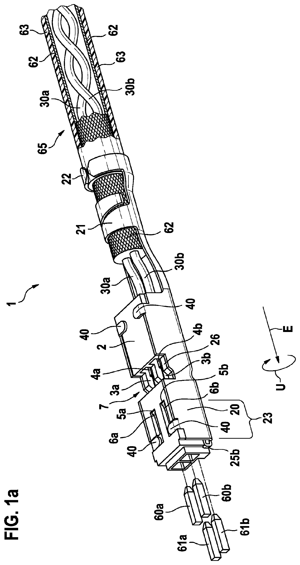
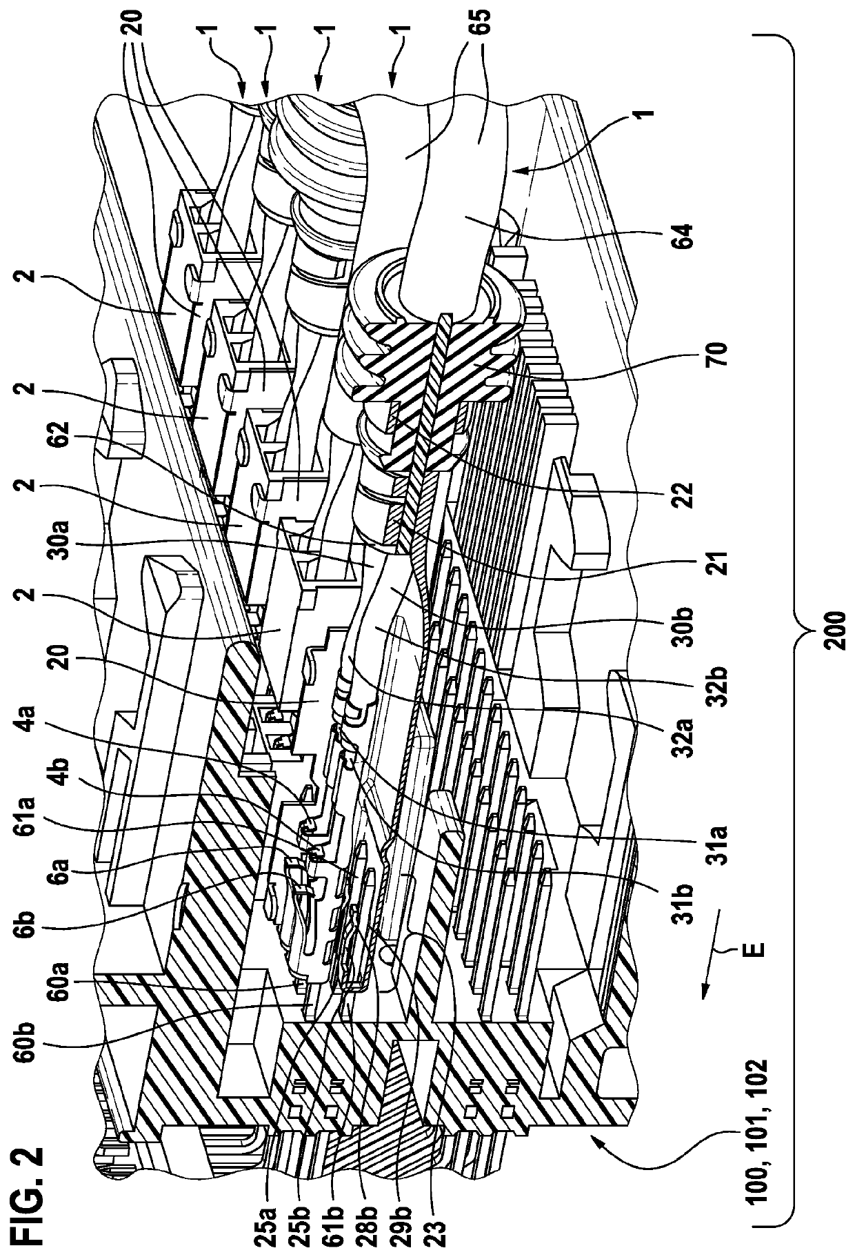
[0047]FIG. 1a shows by way of example a perspective representation of an Ethernet plug connector 1 for a motor vehicle to be plugged together along a plug-in direction E with a mating plug connector 100 (see FIG. 2). Ethernet plug connector 1 includes: a plug connector housing 2 including two contact chambers 3a, 3b and a shield plate 20. One contact element 4a, 4b is situated in each contact chamber 3a, 3b, a counter contact element 60a, 60b being pluggable into each contact element 4a, 4b. One line 30a, 30b is attached to each contact element 4a, 4b at its rear end with respect to plug-in direction E, the two lines 30a, 30b attached to contact element 4a, 4b being combined in a rear section with respect to plug-in direction E to form an

[0048]Ethernet cable 65 and being enclosed by a shield conductor 62, which may be formed, for example, as a shield braid. Lines 30a, 30b extend twisted around one another in Ethernet cable 65 to thus improve the signal quality.

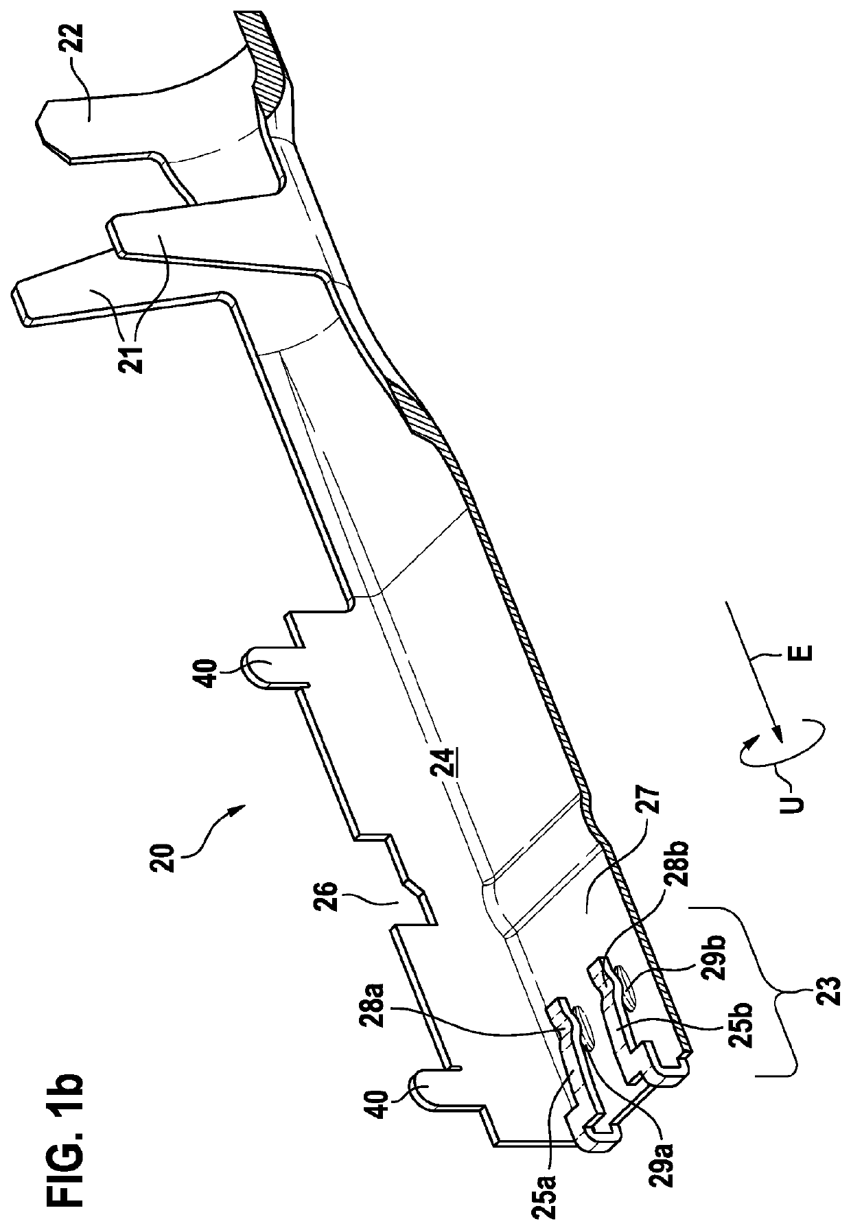
[0049]Shield plate 20 ...


PUM


Abstract

An Ethernet plug connector for a motor vehicle to be plugged together along a plug-in direction with a mating plug connector. The Ethernet plug connector includes a plug connector housing having at least two contact chambers and a shield plate. A contact element is situated in each contact chamber, a counter contact element being pluggable into each contact element. A line is attached to each contact element at its rear end with respect to the plug-in direction. The lines attached to the contact element are combined in a rear section with respect to the plug-in direction to form an Ethernet cable and are enclosed by a shield conductor, the shield plate enclosing the predominant part of the plug connector housing. The shield plate includes a connector, using which it is electrically connected to the shield conductor of the Ethernet cable.

Description

FIELD[0001]The present invention relates to an Ethernet plug connector for a motor vehicle and a plug connector assembly including an Ethernet plug connector.BACKGROUND INFORMATION[0002]Electrical plug connectors, which may be plugged together with complementary, mating plug connectors to form a plug connector assembly are conventional in the related art, for example, for automotive applications.[0003]It is becoming necessary to process a continuously growing amount of information with increasing sensor equipment and on the path to autonomous driving. To manage the amounts of data, the use of Ethernet interfaces and Ethernet lines in the automotive field is being considered. These are, among other things, to enable a sufficiently high data transfer rate with the aid of so-called Ethernet protocols.[0004]Conventional Ethernet plug connectors, so-called RJ-45 plugs, are conventional in the related art. Such an RJ-45 Ethernet plug is described in German Patent Application No. DE 10 201...

Claims


Application Information

Patent Timeline
Patent Type & Authority Applications(United States)
IPC IPC(8): B60R16/02H01R13/6592H01R13/6582H01R4/18
CPCB60R16/0215H01R4/184H01R13/6582H01R13/6592H01R9/0518H01R4/185H01R13/6597
Inventor KRAEMER, THOMAS
Owner ROBERT BOSCH GMBH
Why Eureka
Try Eureka