Diagonal fan having an optimized diagonal impeller

a technology of diagonal impeller and fan blade, which is applied in the direction of machines/engines, mechanical equipment, liquid fuel engines, etc., can solve the problems of large flow outlet losses, and achieve the effect of high pressure generation and efficiency

Active Publication Date: 2022-02-17
EBM PAPST MULFINGEN GMBH & CO KG
View PDF0 Cites 1 Cited by
  • Summary
  • Abstract
  • Description
  • Claims
  • Application Information

AI Technical Summary

Benefits of technology

[0005]The disclosure solves the problem of providing a diagonal fan having an axial outlet flo...

Problems solved by technology

Since the axially centrally disposed motor of diagonal fans has a large motor diameter compared to the installation space and due to the radial extension of the hub,...

Method used


Image

  • Diagonal fan having an optimized diagonal impeller
  • Diagonal fan having an optimized diagonal impeller
  • Diagonal fan having an optimized diagonal impeller

Examples


Embodiment Construction

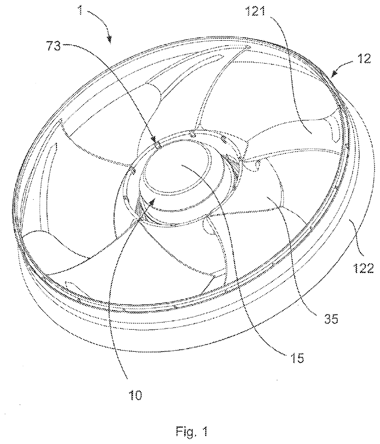
[0028]FIGS. 1 to 5 show various views of an exemplary embodiment of the diagonal fan 1. In the embodiment shown, the diagonal fan 1 includes the electric motor 10 configured as an external rotor motor and the diagonal impeller 12 with its impeller vanes 121 distributed in the circumferential direction and extending radially outwards from the hub 35 disposed about the axis of rotation RA, which vanes are surrounded radially externally by the slinger ring 122.

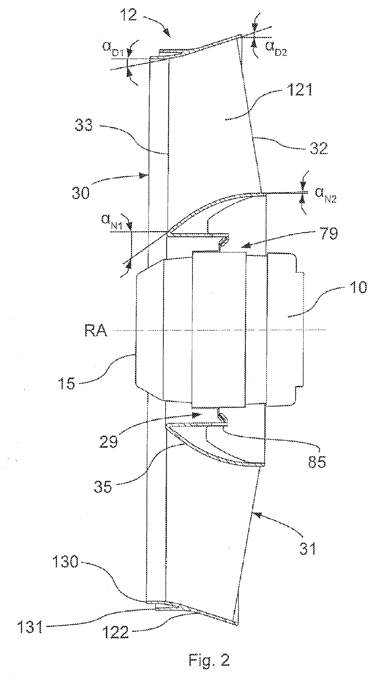
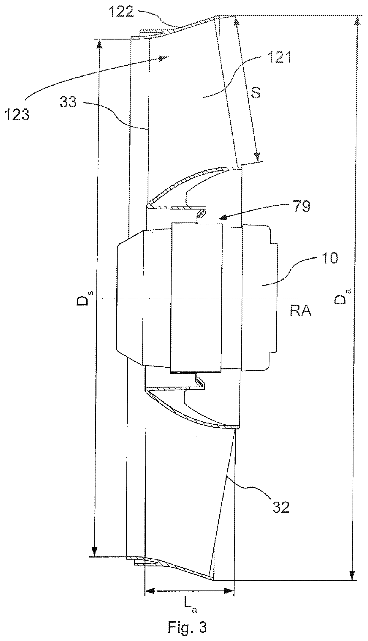
[0029]The diagonal impeller 12 comprises the flow duct between the hub 35 and the inner wall of the slinger ring 122, through which duct the diagonal impeller 12 delivers air from the air inlet 30 to the air outlet 31. The radially internal wall of the flow duct is defined by the shell surface of the hub 35, the radially external wall is defined by the inner wall of the slinger ring 122. The flow angle αD1 formed at the air inlet 30 by the slinger ring 122 relative to the axis of rotation RA is determined to be 10° in the embodim...


PUM


Abstract

A diagonal fan having an electric motor and a diagonal impeller which can be driven about an axis of rotation (RA) by means of the electric motor. The diagonal impeller determines an air inlet and an air outlet and has a hub and impeller vanes which are distributed in the circumferential direction, extend radially outwards from the hub and are surrounded radially externally by a slinger ring. A flow angle αD formed by the slinger ring relative to the axis of rotation (RA) increases from the air inlet to the air outlet, and a flow angle αN formed by the hub relative to the axis of rotation (RA) decreases from the air inlet to the air outlet.

Description

RELATED APPLICATIONS[0001]This application claims priority to and is a 35 U.S.C. § 371 national phase application of PCT / EP2019 / 080093, filed Nov. 4, 2019 and claims priority to German Patent Application No. 10 2018 128 821.2, filed Nov. 16, 2018, the entire contents of which are incorporated herein by reference in their entirety.FIELD[0002]The disclosure relates to a diagonal fan having an optimized diagonal impeller for increasing efficiency.BACKGROUND[0003]Diagonal fans and their use are generally known from prior art, for example, from DE 10 2014 210 373 A1.[0004]Diagonal fans are used in applications with a high demand of air output at higher counterpressure and small installation space, for example in cooling equipment and extractor hoods. Since the axially centrally disposed motor of diagonal fans has a large motor diameter compared to the installation space and due to the radial extension of the hub, the outlet area at the outlet opening is relatively small, which results in...

Claims


Application Information

Patent Timeline
IPC IPC(8): F04D29/38F04D29/32F04D19/00F04D29/54F04D25/06
CPCF04D29/386F04D29/329F04D25/06F04D29/541F04D19/002F04D17/06F04D29/326F04D29/183
Inventor HAAF, OLIVERGEBERT, DANIELDÖRR, JOHANNES
Owner EBM PAPST MULFINGEN GMBH & CO KG
Why Eureka
Try Eureka