Preform with one-piece woven fibrous reinforcement for inter-blade platform

Pending Publication Date: 2022-02-24
SAFRAN
View PDF7 Cites 2 Cited by
  • Summary
  • Abstract
  • Description
  • Claims
  • Application Information

AI Technical Summary

Benefits of technology

[0040]Thus, such a platform allows to meet the functional requirements of blade holding and mechanical strength on the fan rotor disc, and to ensure, thanks to a fibrous reinforcement woven in three-dimension, a simplification of the manufacturing with a composite technology (injected 3D w

Problems solved by technology

The inter-blade platforms and in particular the fixing structure are subject to significant stresses, in particular the centrifugal forces during the rotation of the turbomachine, whic

Method used


Image

  • Preform with one-piece woven fibrous reinforcement for inter-blade platform
  • Preform with one-piece woven fibrous reinforcement for inter-blade platform
  • Preform with one-piece woven fibrous reinforcement for inter-blade platform

Examples


Embodiment Construction

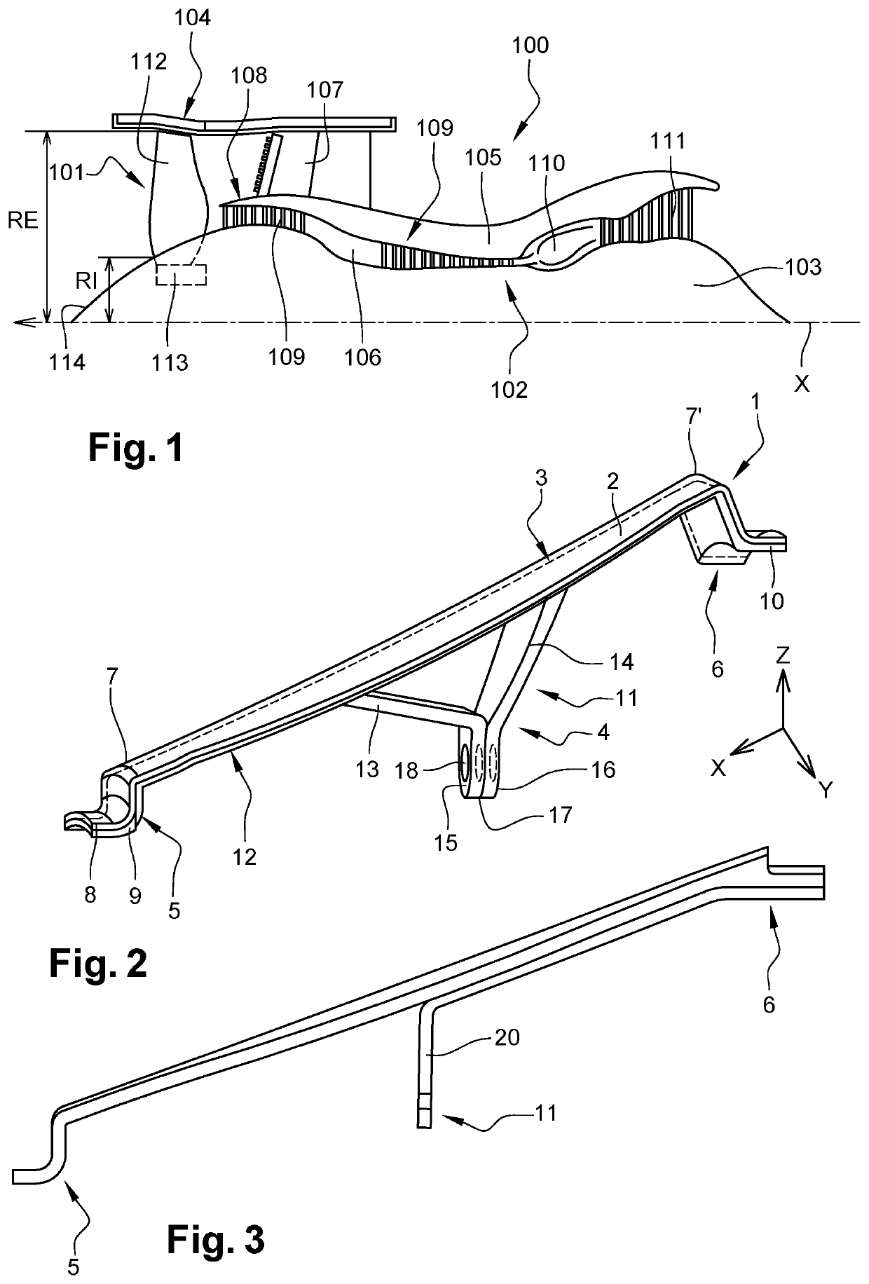
[0060]FIG. 1 illustrates an aircraft turbomachine 100 to which the invention applies. This turbomachine 100 is here a dual flow turbomachine that extends along a longitudinal axis X. Of course, the invention can be applied to other types of turbomachine.

[0061]The turbomachine 100 comprises a fan 101 arranged upstream of a gas generator 102. In the present invention, and in general, the terms “upstream” and “downstream” are defined in relation to the flow of gases in the turbomachine and here along the longitudinal axis of the turbomachine. The gas generator 102 is housed around an annular inner casing 103 while the fan is housed in an annular outer casing 104. These inner and outer casings 103, 104 are separated by an annular inter-duct casing 105 so as to delimit a primary duct 106 and a secondary duct 107. The inter-duct casing 105 carries an annular flow-splitting nose 108 separating the primary duct from the secondary duct.

[0062]The fan 101 generates a primary flow intended to f...


PUM

PropertyMeasurementUnit
Structureaaaaaaaaaa
Lengthaaaaaaaaaa

Abstract

A preform has a fibrous reinforcement woven in one piece by three-dimensional weaving to create a fan inter-blade platform The platform includes an aerodynamic base and a fixing structure having stiffening elements that extend from the aerodynamic base. The preform includes a first fibrous part configured to form the aerodynamic base, second fibrous part configured to at least partially form the stiffening elements of the inter-blade platform, a first connection zone in which the first and second parts are woven together, and a first disconnection zone delimited by a first disconnection line extending in a transverse direction and in which the first and second parts are separated from one another. The first disconnection zone is adjacent to the first connection zone in a longitudinal direction L.

Description

TECHNICAL FIELD OF THE INVENTION[0001]The present invention relates to the field of the manufacturing of turbomachine component made of composite material, such as an inter-blade platform for a turbomachine fan.BACKGROUND[0002]Prior art comprises documents FR-A1-2 988 427, FR-A1-2 988 426 and WO-A2-2013 / 088040).[0003]A turbomachine, and in particular a dual flow turbomachine for aircraft, generally comprises a mobile fan arranged upstream of a gas generator according to the flow of gases in the turbomachine. The fan generates a primary flow intended to flow in a primary duct through the gas generator and a secondary flow intended to flow in a secondary duct around the gas generator. The fan comprises movable fan blades which are carried by a rotor disc centred on a longitudinal axis of the turbomachine. Between each fan blade are arranged inter-blade platforms that extend the inlet cone of the fan.[0004]It is known that these platforms are made of a composite material comprising a f...

Claims


Application Information

Patent Timeline
IPC IPC(8): B29B11/16B29C70/48F01D11/00
CPCB29B11/16B29L2031/082F01D11/008B29C70/48F05D2220/36F05D2230/21F05D2240/80F05D2300/603F05D2300/6034Y02T50/60F05D2230/20
Inventor OBERT, ENRICO GIOVANNICOUPE, DOMINIQUE MARIE CHRISTIANCOLOT, MARC-ANTOINEAUBERT, FABRICE MICHEL FRANÇOIS RENÉMICHELSEN, PIERRE MARTIN
Owner SAFRAN
Why Eureka
Try Eureka