
Pad return spring for a disc brake caliper body

a return spring and disc brake technology, applied in the direction of axially engaging brakes, brake types, actuators, etc., can solve the problems of more frequent replacement, unfavorable aforesaid contrasting needs, and the inability of return springs to meet the aforesaid needs,

Active Publication Date: 2022-02-24
FRENI BREMBO SPA
View PDF3 Cites 3 Cited by
  • Summary
  • Abstract
  • Description
  • Claims
  • Application Information

AI Technical Summary

Benefits of technology

The present invention provides a pad return spring that allows for a reduction in size while maintaining its design load during use. This reduces the risk of exceeding the spring's yielding limit during pad assembly or replacement. The use of several sheet layers also helps decrease the braking torque of the caliper, reduces noise, and wear of the brake pads and brake disc. The sheet layers have a smaller thickness than traditional springs, increasing their elasticity and preventing a risk of exceeding the yielding limit. Overall, the pad return spring provides a design load without increasing its volume.

Problems solved by technology

The pads moving close to the brake disc is undesired since it causes a contact, albeit a slight contact, between pad and disc, which causes a continuous slight friction and therefore a braking action, known as residual braking torque, also at the end of the braking control by the vehicle or motor vehicle driver.
This residual braking torque often is considered undesired since it generates noise, albeit slight noise, caused by the friction action between pads and braking surfaces of the disc, an undesired wear of the pads and of the brake disc, which results in more frequent maintenance for the replacement thereof, and a minimum consumption of fuel for feeding the drive unit also of the albeit minimum energy required to overcome this residual torque.
The known pad return springs do not allow the aforesaid contrasting needs to be simultaneously met.

Method used


Image

  • Pad return spring for a disc brake caliper body
  • Pad return spring for a disc brake caliper body
  • Pad return spring for a disc brake caliper body

Examples


Embodiment Construction

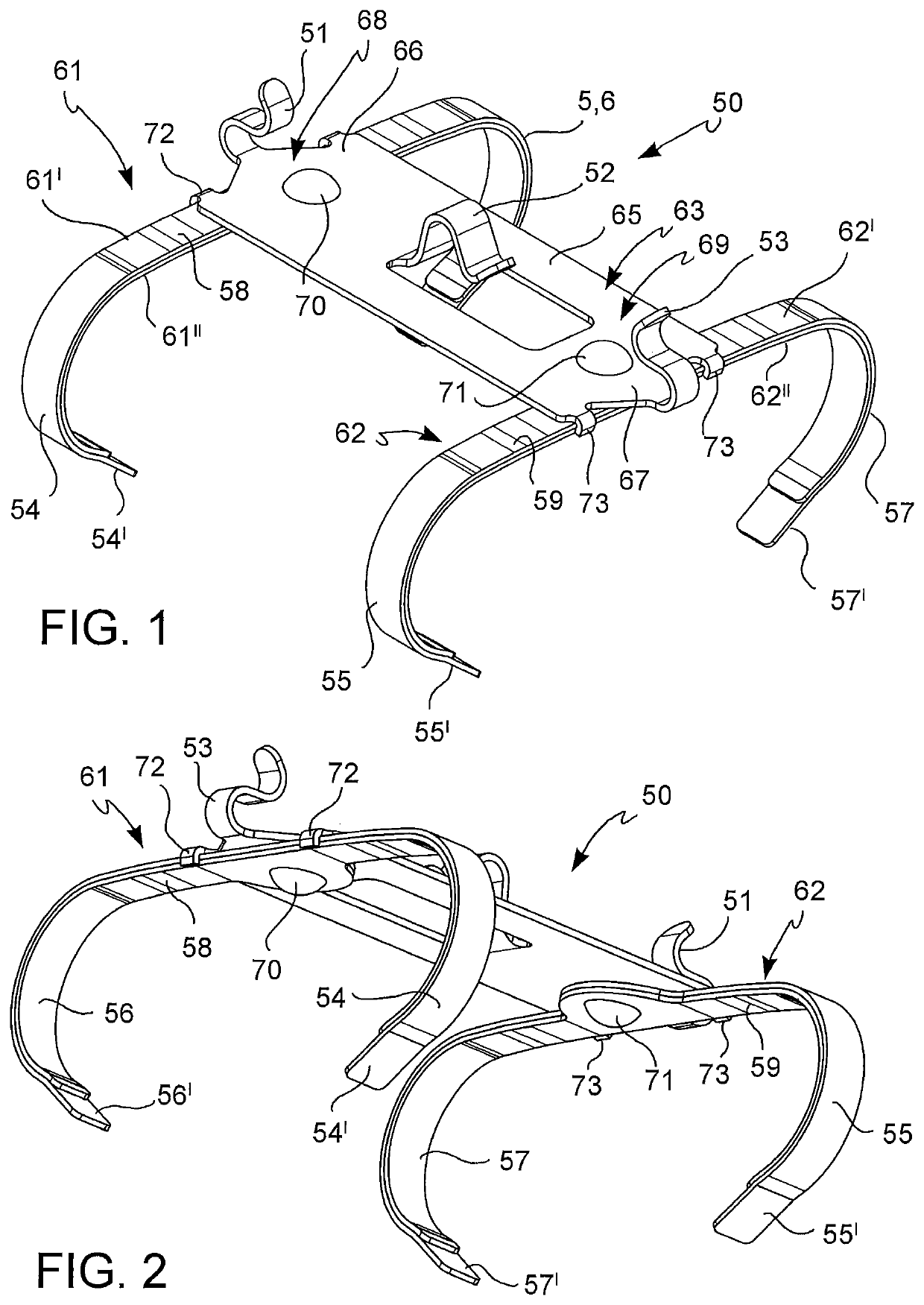
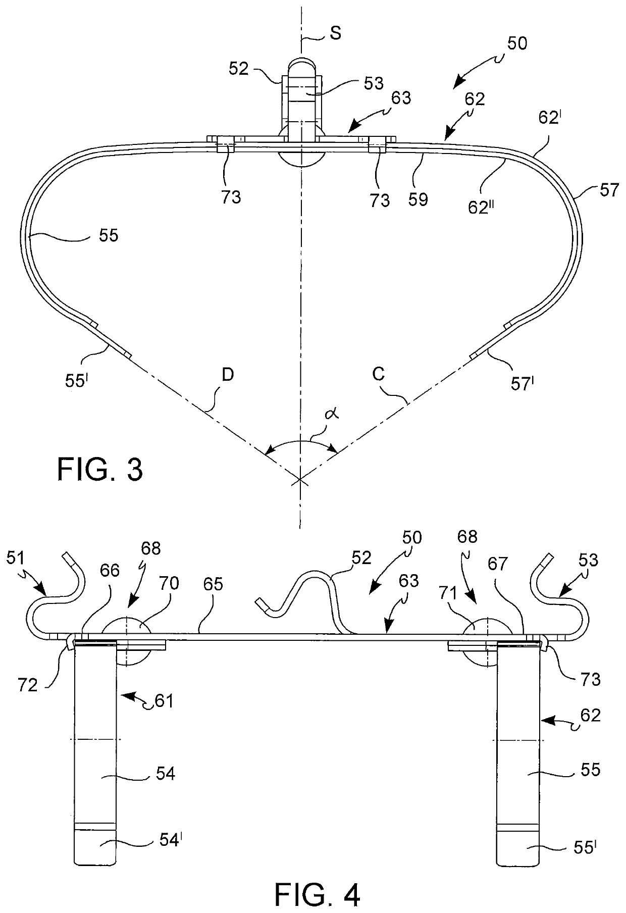
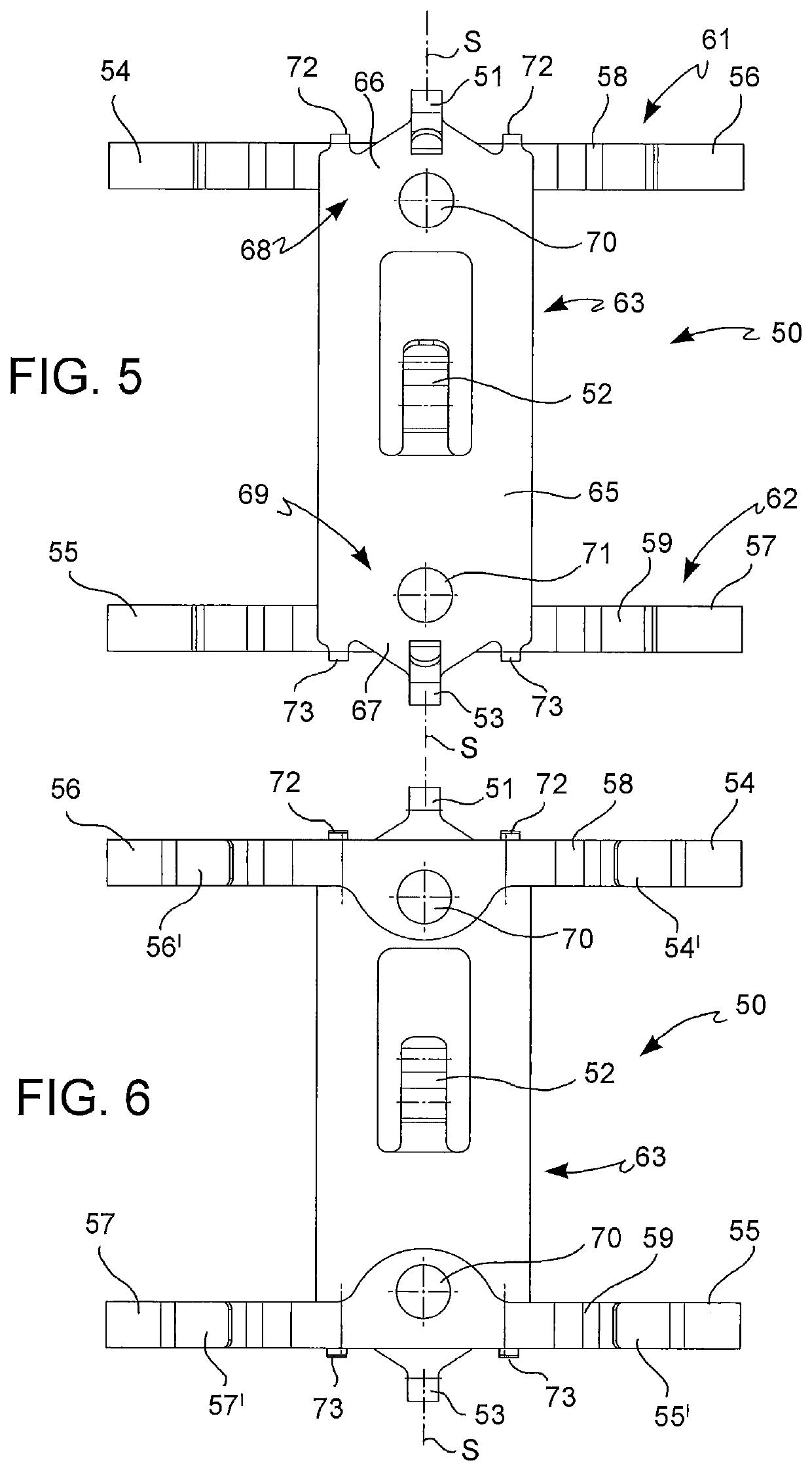
[0058]With reference to the figures, a pad return spring according to the invention for a disc brake caliper body 1 is indicated as a whole by numeral 50.

[0059]Said disc brake caliper body 1 is adapted to straddle a brake disc 2 of the floating type.

[0060]Said brake disc 2 comprises a first braking surface 7 of brake disc and an opposite second braking surface 8 of brake disc.

[0061]Said caliper body 1 comprises a first elongated wheel-side element 3. Said first elongated wheel-side element 3 comprises an outer caliper side 4 of first elongated element and an inner caliper side 5 of first elongated element. Said outer caliper side 4 of first elongated element is adapted to face a vehicle wheel. At least one portion of the inner caliper side 5 of first elongated element is adapted to directly or indirectly face said first braking surface 7 of brake disc by means of a first pad 14.

[0062]Said caliper body 1 comprises a second elongated opposite wheel-side element 9. Said second elongate...


PUM


Abstract

A pad return spring for a caliper body. The caliper body has an elongated element connecting bridge connecting a first elongated wheel-side element to a second elongated wheel-side element and having a middle connecting bridge defining an outer middle bridge side, an inner middle bridge side, a middle bridge disc inlet side, and an opposite middle bridge disc outlet side. The pad return spring has a first and a second pad retraction elements, each defining a middle stretch, a first side stretch influencing the first pad, and an opposite second side stretch influencing the second pad to move the first and second pads away from the first and second braking surfaces at the end of a braking action, and an elongated connecting element connecting the first and second pad retraction elements to each other, and an anchoring device to removably restrain the pad return spring to the middle connecting bridge.

Description

FIELD OF THE INVENTION[0001]The present invention relates to a caliper return spring and a disc brake caliper comprising such a spring.[0002]In particular, the disc brake caliper body in a disc brake caliper body of fixed type does not slide with respect to a support thereof and is adapted to straddle a floating-type brake disc, also known as sliding on a support thereof so as to modify the position thereof along a direction which is coaxial thereto in order to move close to or away from at least one brake pad. Said brake disc has a first braking surface of brake disc and an opposite second braking surface of brake disc. Such a caliper body of fixed type comprises a first elongated wheel-side element, i.e. facing the vehicle wheel, comprising an outer caliper side of first elongated element and an inner caliper side of first elongated element, in which said outer caliper side of first elongated element is adapted to face the vehicle wheel. Said caliper body has at least one portion ...

Claims


Application Information

Patent Timeline
Patent Type & Authority Applications(United States)
IPC IPC(8): F16D65/097F16D55/22F16D65/00F16D55/228
CPCF16D65/0972F16D55/22F16D2055/002F16D55/228F16D65/0075F16D55/2265F16D65/0977F16D2065/1396F16D2127/02
Inventor FUMAGALLI, MARCOMAMBRETTI, MAUROMECOCCI, ANDREAPENDESINI, ALBERTO
Owner FRENI BREMBO SPA
Learn More