Microcurrent-stimulation-therapy apparatus and method

a technology of microcurrent stimulation and therapy apparatus, which is applied in the field of human condition treatment, can solve the problems of deterioration of various retinal tissues, little research on market potential, and chronic pain of millions of individuals, and achieve the effect of maximizing the therapeutic effect and encouraging patient complian

Active Publication Date: 2022-03-03
I LUMEN SCI INC
View PDF0 Cites 1 Cited by
  • Summary
  • Abstract
  • Description
  • Claims
  • Application Information

AI Technical Summary

Problems solved by technology

Chronic pain is a problem for millions of individuals throughout the world.
Macular degeneration results in the deterioration of various retinal tissues in the region of the macula, the central, most sensitive light-sensing area of the retina responsible for detailed central vision.
Because there is currently no approved treatment for dry AMD, little research has been done on the market potential.
There is, however, significant data on the large numbers of people affected by AMD and is estimated to cause about 8.7% of blindness and low vision globally.
Once affected by poor circulation, the RPE cannot efficiently assist the rods and cones in removing the metabolic and photochemical response by-products, which are common during cellular function.
As a result, the photoreceptor cells in the macula enter a dormant, toxic state and do not respond to light.
If normal retinal cellular metabolism is not restored, the cells die and visual acuity is permanently lost.
But, the efficacy of these therapies can be affected by the manual techniques medical professionals use to administer said therapy.
Where patients have significant skin impedance, or there is a poor conductivity, uptake of the stimulation level is limited and will limit the treatment efficacy.
Furthermore, in recalcitrant wounds, it seems likely that the endogenous EFs are askew or absent, in which case the wounds often do not respond to SWC.

Method used


Image

  • Microcurrent-stimulation-therapy apparatus and method
  • Microcurrent-stimulation-therapy apparatus and method
  • Microcurrent-stimulation-therapy apparatus and method

Examples


Embodiment Construction

[0080]Although the following detailed description contains many specifics for the purpose of illustration, a person of ordinary skill in the art will appreciate that many variations and alterations to the following details are within the scope of the invention. Specific examples are used to illustrate particular embodiments; however, the invention described in the claims is not intended to be limited to only these examples, but rather includes the full scope of the attached claims. Accordingly, the following preferred embodiments of the invention are set forth without any loss of generality to, and without imposing limitations upon the claimed invention. Further, in the following detailed description of the preferred embodiments, reference is made to the accompanying drawings that form a part hereof, and in which are shown by way of illustration specific embodiments in which the invention may be practiced. It is understood that other embodiments may be utilized and structural change...


PUM


Abstract

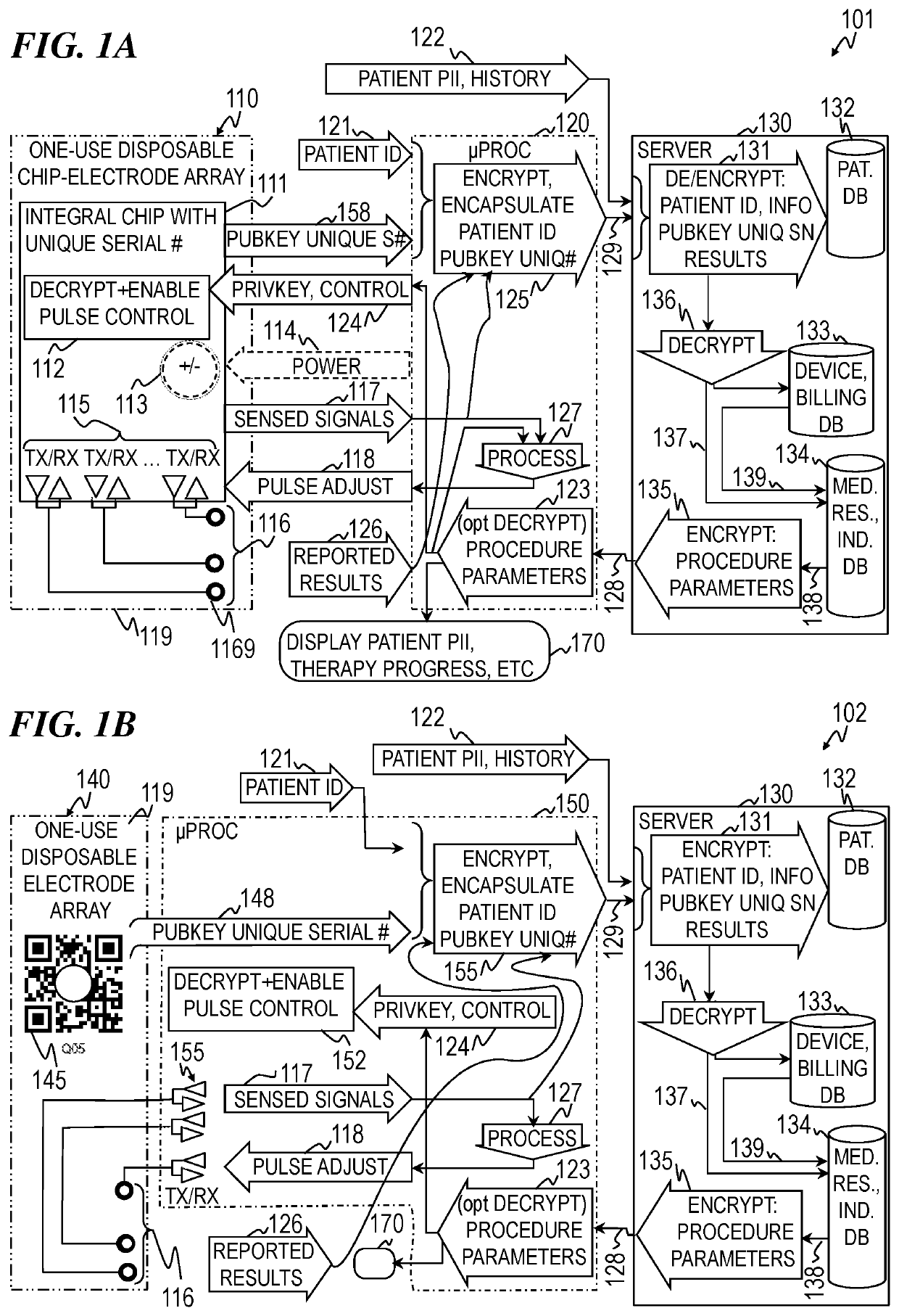
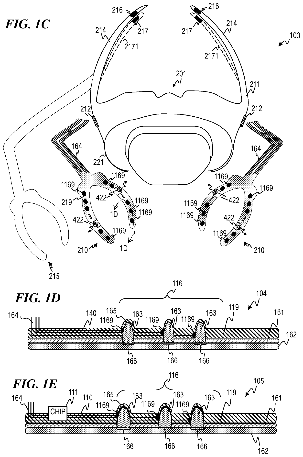
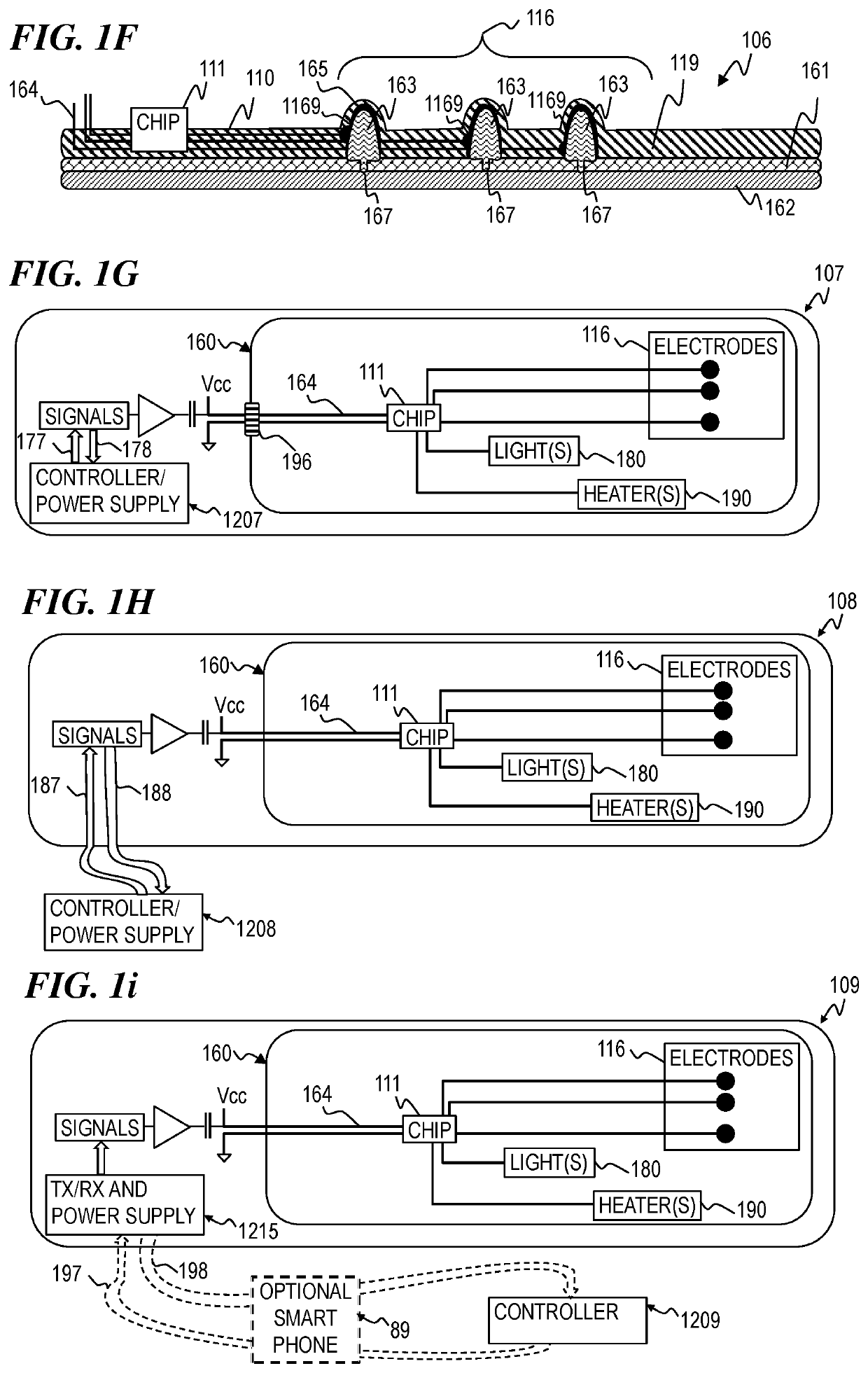
A system and method for applying stimulation therapy to a patient, the system including a first stimulation strip that includes a first elongated portion configured to be placed on the upper eyelid of the first eye of the patient and a second elongated portion configured to be placed on the lower eyelid of the first eye of the patient, wherein the first stimulation strip includes: a first plurality of individually controlled electrodes configured to deliver a microcurrent stimulation therapy to the patient, a first plurality of individually controlled light emitters configured to deliver light stimulation therapy to the patient, and a first plurality of individually controlled heat sources configured to deliver heat therapy to the patient; and a controller operatively coupled to the first stimulation strip and configured to control delivery of the microcurrent stimulation therapy, the light stimulation therapy, and the heat therapy.

Description

CROSS-REFERENCE TO RELATED APPLICATIONS[0001]This application claims priority benefit, including under 35 U.S.C. § 119(e), of U.S. Provisional Patent Application 62 / 783,116 filed Dec. 20, 2018 by Marshall T. Masko, et al., titled “Apparatus and Method for Microcurrent Stimulation Therapy,” which is incorporated herein by reference in its entirety.FIELD OF THE INVENTION[0002]The present invention relates to treatment of a human condition and more particularly to a system and method for applying bio-electric microcurrent-stimulation therapy, light-stimulation therapy, and / or heat therapy to the human body.BACKGROUND OF THE INVENTION[0003]Chronic pain is a problem for millions of individuals throughout the world. One method of treating such pain is to provide microcurrent stimulation around or near the areas where the pain is occurring. Microcurrent, which typically is defined as current below 1 milliamp, can provide rapid and long-lasting pain relief for a wide variety of pain syndrom...

Claims


Application Information

Patent Timeline
Patent Type & Authority Applications(United States)
IPC IPC(8): A61N1/36A61N1/04A61N5/06
CPCA61N1/36046A61N1/3603A61N2005/0648A61N5/06A61N1/0456G16H40/67G06F3/012G16H20/30G16H10/60G06F21/6245
Inventor MASKO, MARSHALL T.MOWERY, BLAIR P.VELURE, JOHN C.LEMAIRE, CHARLES A.
Owner I LUMEN SCI INC
Why Eureka
Try Eureka