
Ventilator system with multiple airflow control lumens

a ventilator and airflow technology, applied in the field of ventilator systems, can solve the problems of infection or other diseases spreading through the patient's airways, dcas suspended in dead space are generally not accessible to inhaled medications or the human body's defense systems, and achieve the effects of reducing dead space, reducing dead space in the patient's airways, and increasing the clearance of dead spa

Active Publication Date: 2022-03-10
KILJANEK LUKASZ R
View PDF0 Cites 0 Cited by
  • Summary
  • Abstract
  • Description
  • Claims
  • Application Information

AI Technical Summary

Benefits of technology

This patent describes a ventilator system that reduces dead space in a patient's airways by using separate airways for each lung and / or bronchi. The system also includes expiratory lumens to remove expiratory gases. This reduces the risk of cross-infection and contamination between different parts of the patient's airways. Overall, this technique improves respiratory care for patients with lung and airway diseases.

Problems solved by technology

Respiratory conditions, such as diseases, injuries, or disabilities, can all increase dead space in the airways of patients, for example by impairing a patient's ability to inhale and / or exhale.
Disease-causative agents (DCAs) can move throughout dead space in a patient's airways, which can cause infections or other diseases to spread throughout the patient's airways.
DCAs suspended in dead space are generally not accessible to inhaled medications or to the human body's defense systems (e.g., immune cells and antibodies).

Method used


Image

  • Ventilator system with multiple airflow control lumens
  • Ventilator system with multiple airflow control lumens
  • Ventilator system with multiple airflow control lumens

Examples


Embodiment Construction

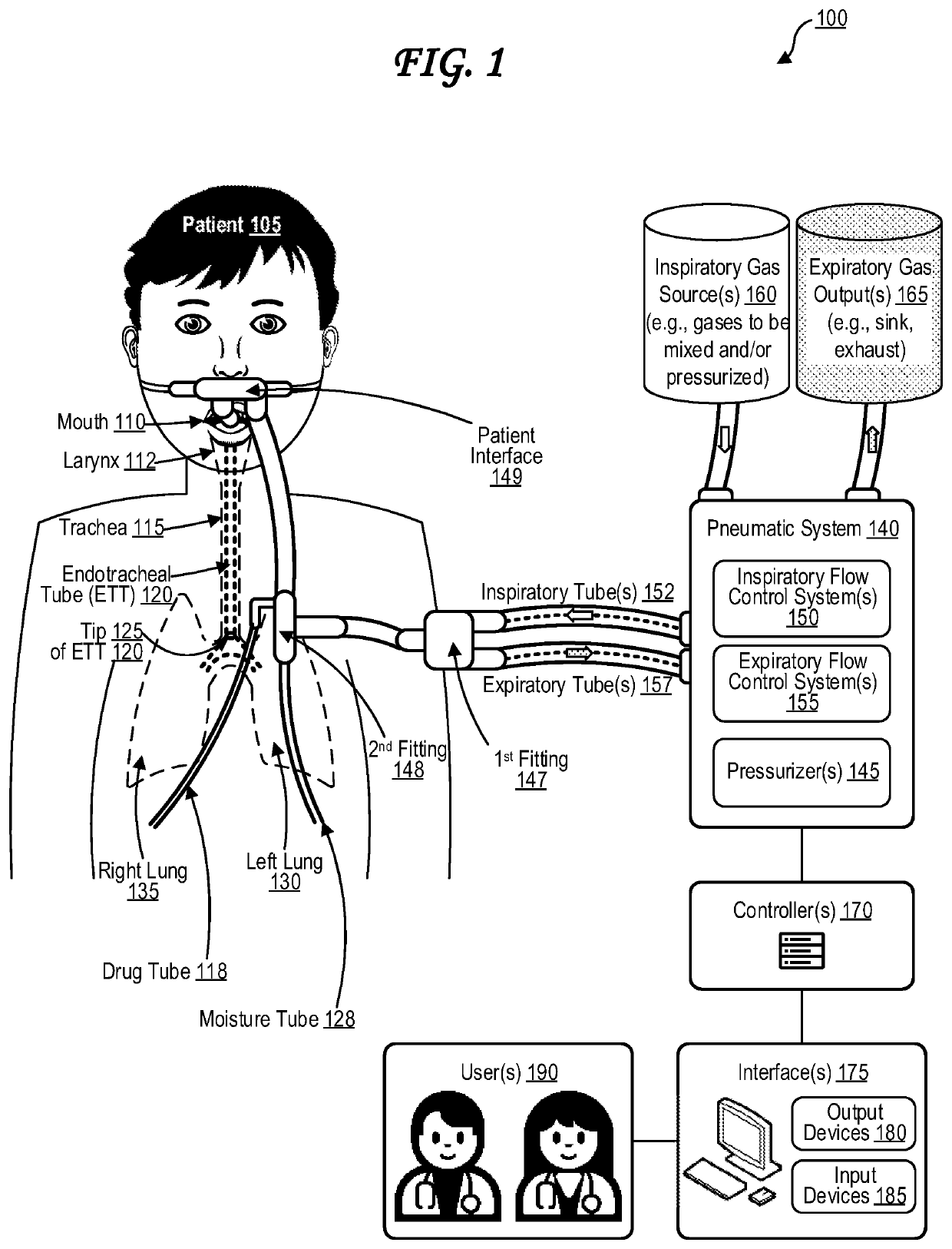
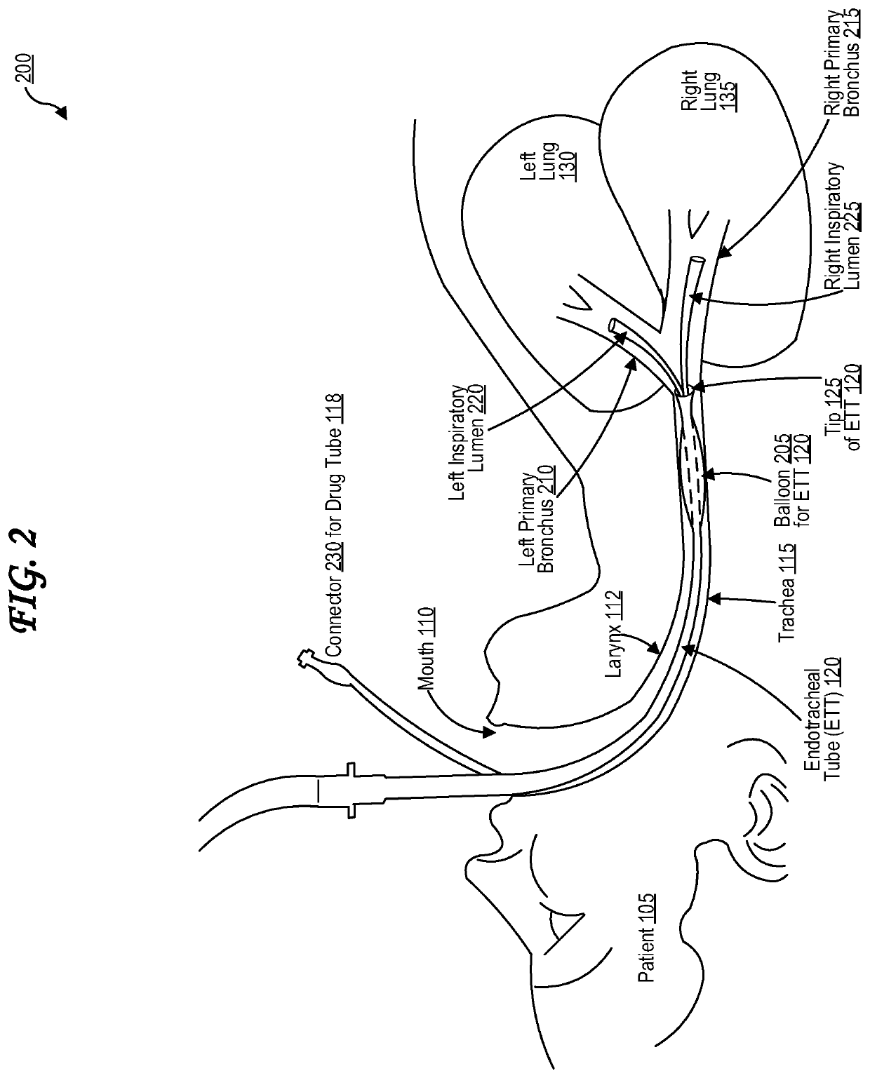
[0035]A ventilator is a life support machine that can be used to assist a patient with breathing. A ventilator generally includes an endotracheal tube that is inserted via mouth into the patient's trachea. A ventilator can mechanically provide an inspiratory gas into the patient's airways. A ventilator can mechanically evacuate an expiratory gas from the patient's airways. A ventilator may be used, for example, when a patient is having trouble breathing on their own due to an infection, an injury, a disease, a physical handicap, a physical disability, weakness, sedation, use of paralyzing anesthetics, another medical condition, another physical condition, another anatomical condition, or a combination thereof.

[0036]A patient's lungs and airways can become infected with and / or otherwise affected by a disease-causative agent (DCA). DCAs can include, for example, bacteria, fungi, viruses (e.g., virions, viral agents), parasites, protozoa, helminths, prions, toxins, synthetic toxicants,...


PUM


Abstract

Ventilator system with multiple inspiratory lumens is provided. The inspiratory lumens are configured so that separate inspiratory lumens provide inspiratory gas mixtures to separate portions of a patient's airways, for instance to separate lungs and / or bronchi. The ventilator system can include one or more expiratory lumens to evacuate expiratory gases from airways. The use of separate inspiratory lumen(s), with expiratory lumen(s), allows for functional separation of structural portions of the lungs, and maintenance of continuous or almost continuous flow through at least part of respiratory cycle via inspiratory and expiratory lumens. This can further reduce dead space and clear suspended therein diseases causative agents with improvement in outcomes, reduce risk of cross-contamination or cross-infection between different parts of airways, for example such as cross-infection from one lung lobe to another lobe or. The ventilator system allows for independent titration of PEEP, pCO2 and pO2 with no need for permissive hypercapnia.

Description

CROSS-REFERENCE TO RELATED APPLICATIONS[0001]The present application claims the priority benefit of U.S. provisional application No. 63 / 075,327 filed Sep. 8, 2020 and entitled “Methods and Devices to Decrease Functional and Anatomical Dead Space and Improve Outcomes in Severe, Infectious Process Involving Lungs;” U.S. provisional application No. 63 / 075,555 filed Sep. 8, 2020 and entitled “Methods and Devices to Decrease Functional and Anatomical Dead Space and Improve Outcomes in Severe, Infectious Process Involving Lungs;” and U.S. provisional application No. 63 / 077,037 filed Sep. 11, 2020 and entitled “Methods and Devices to Decrease Functional and Anatomical Dead Space and Improve Outcomes in Severe, Infectious Process Involving Lungs;” the disclosures of which are all hereby incorporated by reference in their entireties.BACKGROUND1. Field[0002]The present teachings are generally related to ventilator systems. More specifically, the present teachings relate to ventilator systems ...

Claims


Application Information

Patent Timeline
IPC IPC(8): A61M16/04A61M16/12A61M16/20
CPCA61M16/042A61M16/12A61M2202/0225A61M16/208A61M16/0463A61M16/1055A61M16/107A61M16/0093A61M16/0434A61M16/0486A61M16/0404A61M16/1065A61M16/16A61M16/1075A61M16/209A61M2205/3331A61M16/024A61M16/0808A61M2202/0266A61M2202/0208A61M16/14A61M11/00A61M16/0816A61M2230/432A61M2230/205A61M2230/30A61M2230/04A61M2230/50A61M2205/3375A61M2205/581A61M2205/583A61M2205/505A61M16/0057A61M2205/3592A61M2205/7563A61M2205/3368A61M2016/0039A61M2016/0042A61M2016/0027A61M16/161A61M2016/1025A61M2016/103A61M2016/1035A61M2230/435A61M2230/437A61M16/0883A61M2205/3344A61M16/1005A61M16/0009A61M16/0051A61M2205/3553A61M16/106
Inventor KILJANEK, LUKASZ R.
Owner KILJANEK LUKASZ R
Learn More