Gas turbine engine with airflow measurement system

Pending Publication Date: 2022-03-10
ROLLS ROYCE PLC
View PDF1 Cites 1 Cited by
  • Summary
  • Abstract
  • Description
  • Claims
  • Application Information

AI Technical Summary

Benefits of technology

The present invention is a turbofan gas turbine engine that has a bypass airflow measurement system. This system offers various technical benefits, such as improving engine performance and reducing fuel consumption. Overall, this engine offers more efficient and effective operation.

Problems solved by technology

It is currently not possible to directly measure the thrust produced by a gas turbine engine during flight.
Using post-fan pressure, i.e. the pressure air directly downstream of the fan rotor, as a parameter to be correlated with the thrust produced by a gas turbine engine, has its limitations.
That applies to both static and stagnation pressure and therefore any absolute error in pressure measurements becomes an increasing fractional error in thrust setting.
Secondly, stagnation pressure measurements are characterised by a large sampling uncertainty behind the fan outlet guide vanes (OGVs).
This leads to most engines over-thrusting, which increases the rate with which an engine will deteriorate, reduces the engine's time on wing, and unnecessarily lowers the life of the engine for its owner.
That means that a core-based power setting parameter has to assume a minimum-performing low pressure system, which results in over-thrusting for the majority of engines.
Furthermore, the samples in the limited region may not be representative of the bulk airflow, for example, it may be influenced by the boundary layer of the airflow along the casing.
Therefore, the correlation model may not be robust to a changing operating condition and so the calculation of the bulk airflow may not be accurate.
An electric current is sent through the wire, causing the wire to become hot.

Method used


Image

  • Gas turbine engine with airflow measurement system
  • Gas turbine engine with airflow measurement system
  • Gas turbine engine with airflow measurement system

Examples


first embodiment

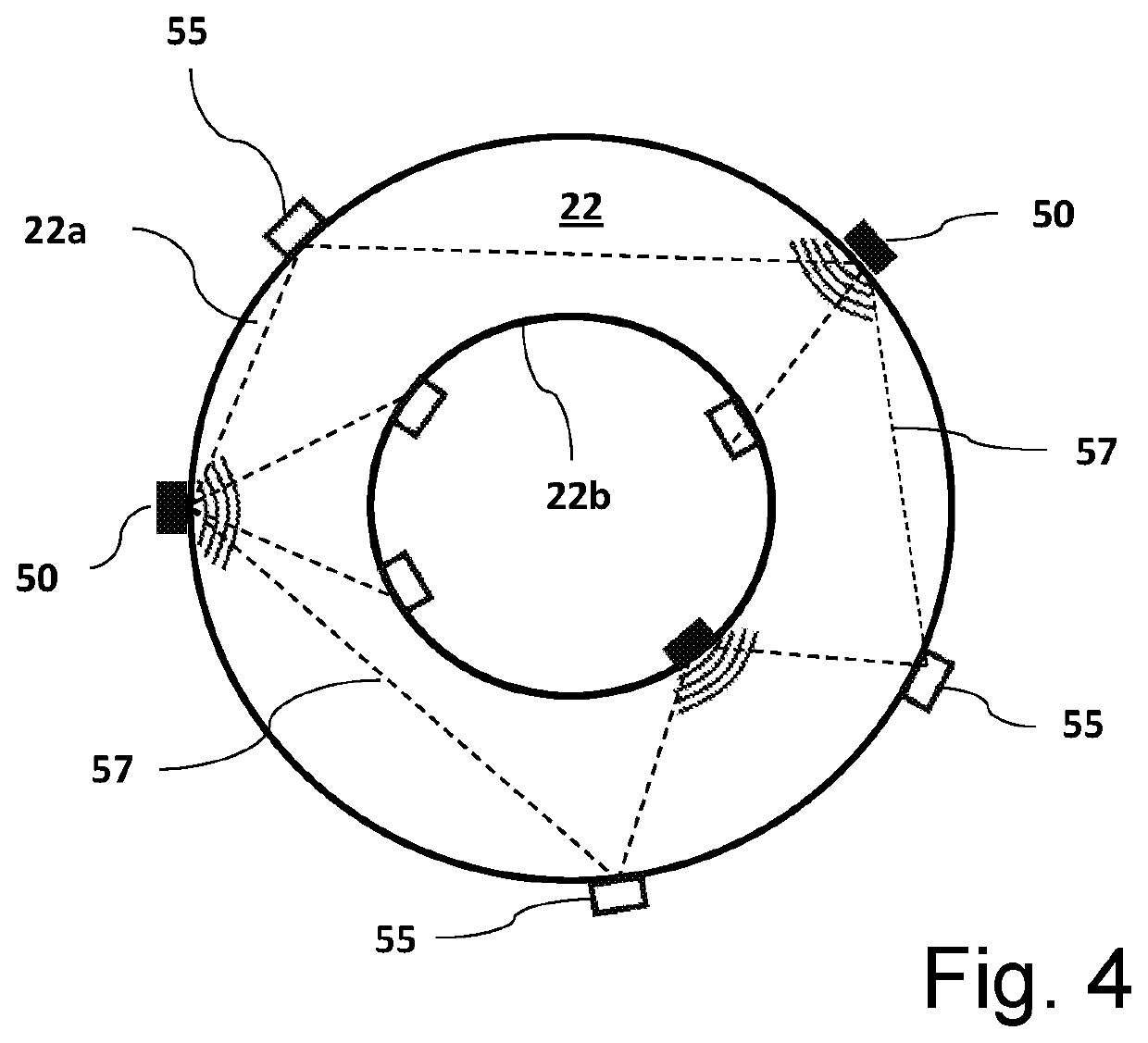
[0080]FIGS. 4 and 5 show different views of a turbofan gas turbine engine of the present disclosure equipped with a bypass airflow measurement system. The bypass airflow measurement system comprises multiple ultrasonic sensors arranged within the bypass duct 22 of a gas turbine engine 10.

[0081]FIG. 4 is a schematic cross-sectional view of a bypass duct 22 of a turbofan gas turbine engine 10 viewed down the principal and rotational axis of the engine. The bypass duct 22 is defined by an outer bypass wall 22a and an inner bypass wall 22b. The bypass duct is equipped with multiple ultrasonic sensors, i.e. several acoustic transmitters 50 and several acoustic receivers 55. Two acoustic transmitters 50 are provided on the outer bypass wall 22a and one acoustic transmitter 50 is provided on the inner bypass wall 22b. Three acoustic receivers 55 are provided on the outer bypass wall 22a and three acoustic receivers 55 are provided on the inner bypass wall 22b. The ultrasonic sensors 50, 55...

second embodiment

[0084]FIGS. 6 and 7 show different views of a turbofan gas turbine engine of the present disclosure equipped with a bypass airflow measurement system.

[0085]FIG. 6 is a schematic cross-sectional view of a bypass duct 22 of a gas turbine engine 10 viewed down the principal and rotational axis of the engine. The bypass duct 22 is defined by an outer bypass wall 22a and an inner bypass wall 22b and the bypass duct is equipped with multiple ultrasonic sensors, i.e. several acoustic transmitters 50 and several acoustic receivers 55. The ultrasonic sensors are located at a substantially specific axial position on an ultrasonic sensor plane that is substantially perpendicular to the bypass flow of the gas turbine engine. The port and starboard sensors can be in separate axial positions however the established lines of sight should be on a single plane. In the axial machine shown the ultrasonic sensor plane is divided along a vertical plane that passes along the principal and rotational axis...


PUM


Abstract

A turbofan gas turbine engine having a bypass duct, and a bypass airflow measurement system. The bypass airflow measurement system comprises: at least one acoustic transmitter configured to transmit an acoustic waveform across the bypass duct of the gas turbine engine though which a bypass airflow passes to at least one acoustic receiver; where the at least one acoustic transmitter and the at least one acoustic receiver are located on an axial plane that is substantially perpendicular to the bypass flow. A method of measuring bypass airflow properties of a turbofan gas turbine engine is also described.

Description

CROSS-REFERENCE TO RELATED APPLICATIONS[0001]This specification is based upon and claims the benefit of priority from United Kingdom patent application number GB 2014210.5 filed on Sep. 10, 2020, the entire contents of which is incorporated herein by reference.BACKGROUNDField of the Disclosure[0002]The present disclosure relates to a gas turbine engine that has a bypass airflow measurement system, and a method of measuring bypass airflow within a gas turbine engine.Description of the Related Art[0003]In an axial flow engine, for example, a gas turbine engine, measurement of the properties of the air flowing into or through the engine can be used to determine the performance of the engine. For example, the average flow velocity or the mass flow of the airflow can be used to calculate the performance and / or efficiency of the engine.[0004]It is currently not possible to directly measure the thrust produced by a gas turbine engine during flight. Therefore, prior to entering into service...

Claims


Application Information

Patent Timeline
IPC IPC(8): F02K3/075F02C7/36F02C9/28F02C9/18F02K3/06
CPCF02K3/075F02C7/36F02C9/28F02C9/18F02K3/06F05D2270/80F05D2270/112F05D2270/306F05D2260/606F05D2220/36F05D2260/40311F05D2270/303F02C3/04G01M15/14F01D17/08G01P5/175F01D21/003G01F1/667F05D2210/30F05D2250/80F05D2270/3061F05D2270/806G01F5/00G01F15/02G01F15/063Y02T50/60G01F1/66
Inventor KYRITSIS, VASILEIOSBRISTOW, MAURICELOFTUS, PETER
Owner ROLLS ROYCE PLC
Why Eureka
Try Eureka