Oil system

Active Publication Date: 2021-06-17
ROLLS ROYCE PLC
View PDF5 Cites 0 Cited by
  • Summary
  • Abstract
  • Description
  • Claims
  • Application Information

AI Technical Summary

Benefits of technology

The patent describes an oil system for a gas turbine engine that includes a main oil tank, a supplementary oil tank, and a pump to supply oil to the engine. The supplementary tank is equal in size or larger than the steady state oil gulp of the engine. The oil system also includes oil scavenging pumps and an electronic controller to manage the oil levels. The oil system can be controlled by the engine's electronic controller. The gas turbine engine may have a gearbox that drives the fan, and the oil system can be used in a gas turbine engine with a gearbox. The technical effects of the oil system include improved oil level control and efficient oil usage.

Problems solved by technology

The un-usable oil volume (VUNB) is also the result of the oil migration within the oil system due to filling of the pipe work, bearing chambers and changes in the engine power.
This therefore presents a technical problem that needs to be overcome.

Method used


Image

  • Oil system
  • Oil system
  • Oil system

Examples


Embodiment Construction

[0054]Aspects and embodiments of the present disclosure will now be discussed with reference to the accompanying figures. Further aspects and embodiments will be apparent to those skilled in the art.

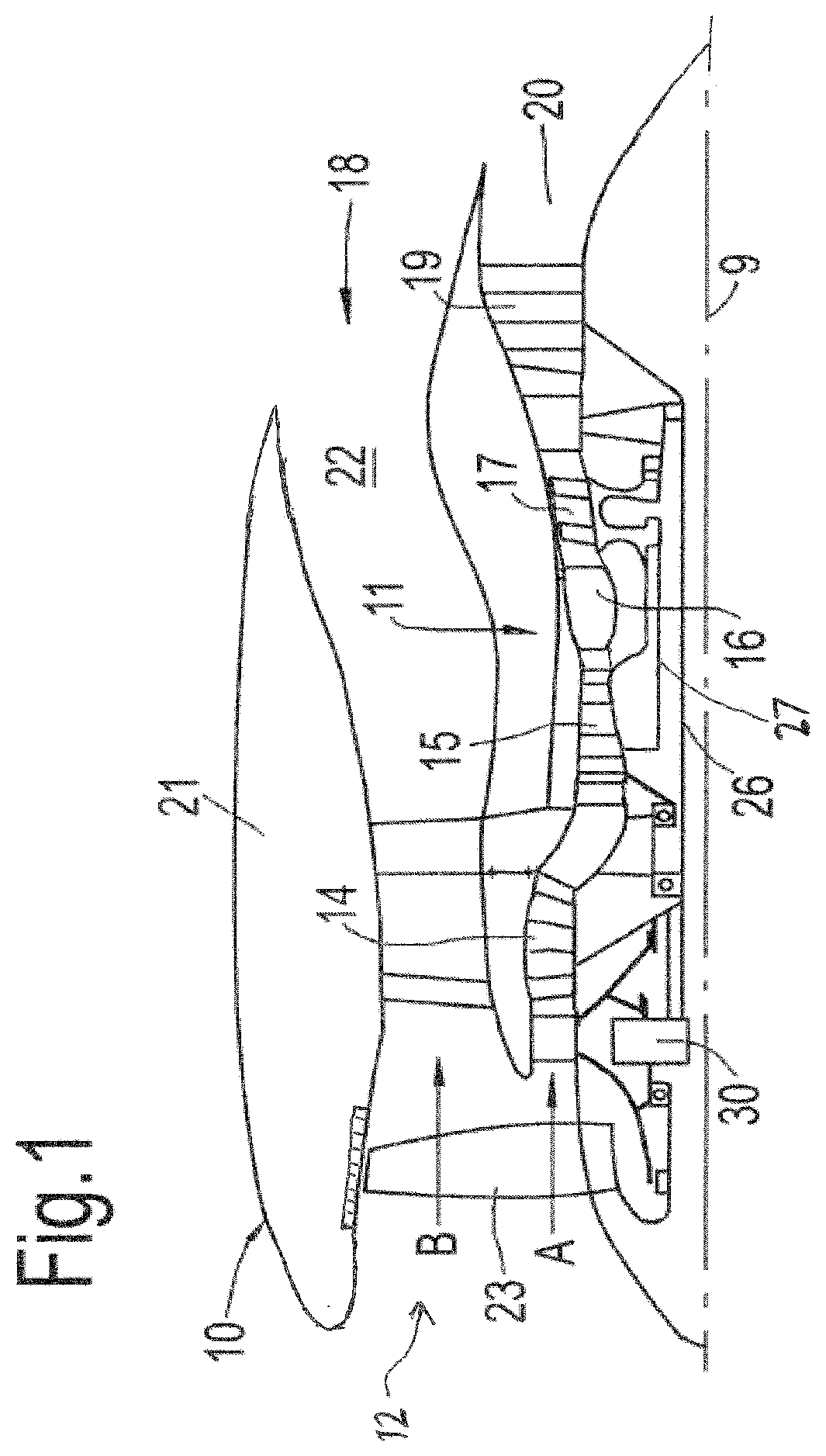
[0055]FIG. 1 illustrates a gas turbine engine 10 having a principal rotational axis 9. The engine 10 comprises an air intake 12 and a propulsive fan 23 that generates two airflows: a core airflow A and a bypass airflow B. The gas turbine engine 10 comprises a core 11 that receives the core airflow A. The engine core 11 comprises, in axial flow series, a low pressure compressor 14, a high-pressure compressor 15, combustion equipment 16, a high-pressure turbine 17, a low pressure turbine 19 and a core exhaust nozzle 20. A nacelle 21 surrounds the gas turbine engine 10 and defines a bypass duct 22 and a bypass exhaust nozzle 18. The bypass airflow B flows through the bypass duct 22. The fan 23 is attached to and driven by the low pressure turbine 19 via a shaft 26 and an epicyclic gearbox 3...


PUM


Abstract

An oil system for a gas turbine engine and a method of supplying oil to the system. The oil system includes a main oil tank connected by oil lines with a supplementary oil storage tank, which has an actuator, and that are connected to one oil pump for supplying oil to the gas turbine engine. The supplementary oil storage tank is equal in size or larger than a steady state oil gulp of the system. The method includes supplying oil from a main oil tank through a pipe line using an oil pump, detecting the oil level in the oil system and determining if additional oil is required or requires removing using a sensor and an electronic controller, and transmitting a signal to an actuator to supply or remove oil to and from the pipe lines in the oil system from or into a supplementary oil storage tank.

Description

FIELD OF THE DISCLOSURE[0001]The present disclosure relates to an oil storage system. In particular the disclosure relates to a supplementary oil storage system, for example for use in a gas turbine engine.BACKGROUND OF THE DISCLOSURE[0002]In a typical oil system used in a gas turbine engine the oil is stored within the oil tank and lines. The oil is moved around the system via an oil feed pump that takes the oil from the oil tank and passes through a feed filter and into a heat exchanger before going to the desired part of the engine. It is removed from the engine via oil scavenge pumps and passes through a scavenge filter before returning to the oil tank. When the gas turbine engine is a turbofan engine, the oil tank and the oil pumps are typically positioned within the fan case.[0003]The oil tank is typically sized to ensure that the minimum enclosed volume is equal to the sum of the following: the expansion space which is the required volume for the expansions of the oil; the us...

Claims


Application Information

Patent Timeline
IPC IPC(8): F02C7/06F01D25/20F01D21/00
CPCF02C7/06F01D25/20F05D2270/54F05D2260/98F01D21/003F01D25/18F05D2240/50Y02T50/60
Inventor WANG, YI
Owner ROLLS ROYCE PLC
Why Eureka
Try Eureka