Visualization of massive 3D models in interactive editing workflows

a visualization and workflow technology, applied in the field of computer-based three-dimensional (3d) modeling, can solve the problems of difficult to provide acceptable results in interactive editing workflows, out-of-date polygon meshes, and large scope of 3d models

Active Publication Date: 2022-03-10
BENTLEY SYST INC
View PDF2 Cites 1 Cited by
  • Summary
  • Abstract
  • Description
  • Claims
  • Application Information

AI Technical Summary

Benefits of technology

[0009]In various embodiments, techniques are provided for visualizing a 3D model using a hybrid approach that is tile-based for unmodified elements and element-based for modified elements. The hybrid approach may address the scaling issues of pure element-based approaches and the tile in

Problems solved by technology

Some 3D models may be massive in scope, such that their database may include a huge number of elements.
Such scope may present a number of challenges in visualizing (i.e. rendering a view of) the 3D model given the constraints of computing hardware.
When a user interacts with the 3D model and changes the geometry of an element, the polygon mesh becomes out of date.
However, both types of approaches have struggled to provide acceptable results in interactive editing workflows when used with massive 3D models.
However, element-based approaches scale poorly as the number of elements increase.
Each draw call has a performance cost which negatively impacts framerate, such that as the number of draw calls increases framerate decreases.
In the first case, interactivity is compromised as the user is forced to wait for the view to update.
Elements “drop out” and then gradually “pop in”, which may be highly distracting to a user.
The issue may be exacerbated if view perspective or element geometry is rapidly changed, such that process must restart before there is sufficient time to catch up, as more and more of the

Method used


Image

  • Visualization of massive 3D models in interactive editing workflows
  • Visualization of massive 3D models in interactive editing workflows
  • Visualization of massive 3D models in interactive editing workflows

Examples


Embodiment Construction

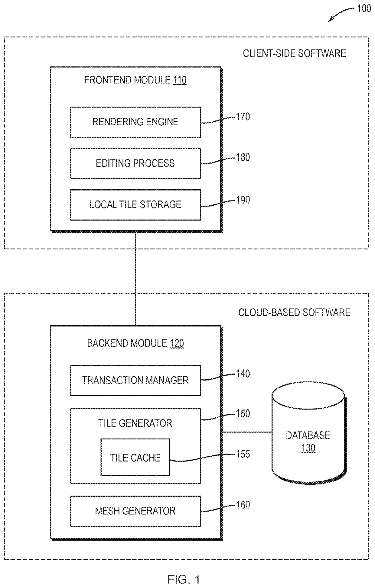
[0024]FIG. 1 is a high-level block diagram of an example software application 100 for visualizing a 3D model. The application 100 may be a portion of an infrastructure modeling software architecture, in which case the 3D model may be a 3D model that represents infrastructure (e.g., buildings, plants, roads, railways, bridges, utility and communications networks, etc.). Alternatively, the application 100 may be a portion of another type of software architecture and the 3D model may represent other types of objects in the real world. The application is divided into a frontend module 110 and a backend module 120. The frontend module 110 and the backend module 120 may be executed on the same computing device, or on different computing devices. In one implementation, the frontend module 110 may be part of client-side software executing on a computing device local to an end-user which communicates via a network (e.g., the Internet) with the backend module 120 that is part of cloud-based s...


PUM


Abstract

In example embodiments, techniques are provided for visualizing a 3D model in an interactive editing workflow. A user modifies one or more elements of a model of the 3D model, by inserting one or more new elements having geometry, changing the geometry of one or more existing elements and/or deleting one or more existing elements having geometry. An updated view of the 3D model is then rendered to reflect the modification to the one or more elements in part by obtaining, for each new element or changed existing element of the model visible in the view, a polygon mesh that represents geometry of the individual element, obtaining a set of tiles that each include a polygon mesh that represent collective geometry of a set of elements intersecting the tile's volume, displaying the polygon mesh for each new element or changed existing element, and displaying the set of tiles while hiding any deleted or changed existing elements therein.

Description

BACKGROUNDTechnical Field[0001]The present disclosure relates generally to computer-based three-dimensional (3D) modeling, and more specifically to visualizing 3D models in the course of interactive editing workflows using a 3D modeling software application.Background Information[0002]Computer-based 3D modeling plays an increasingly important role in the design, construction and / or operation of objects in the real world. While 3D modeling is used in many fields, it is particularly important in the field of infrastructure, where it is commonly used in the design, construction and / or operation of buildings, plants, roads, railways, bridges, utility and communications networks, and other types of infrastructure.[0003]A 3D model may be maintained using records of a database that include a number of elements. As used herein, the term “element” refers to a record that represents (i.e. “models”, in a colloquial sense of the term) an entity in the real-world. Some 3D models may be massive i...

Claims


Application Information

Patent Timeline
IPC IPC(8): G06T19/20
CPCG06T19/20G06T2200/24G06T2219/2021G06T15/005G06T17/005
Inventor CONNELLY, PAUL
Owner BENTLEY SYST INC
Why Eureka
Try Eureka