Gas leak sensing device, setting method for gas leak sensing, gas leak sensing method, and tangible medium

a technology for gas leak sensing and setting methods, which is applied in the direction of measurement devices, measuring/machine measurement, instruments, etc., can solve the problems of unreliable leak sensing devices, gas leak sensing when clamped, and taking as much time as normal gas leak sensing, so as to improve the reliability of gas leak sensing

Active Publication Date: 2022-03-17
COSMO INSTR
View PDF3 Cites 1 Cited by
  • Summary
  • Abstract
  • Description
  • Claims
  • Application Information

AI Technical Summary

Benefits of technology

[0020]Given these issues, an object of the present invention is to provide a technique that improves the reliability of gas leak sensing.
[0023]The gas leak sensing device and gas leak sensing method of the present invention can improve the reliability of gas leak sensing because they can test the gas leak sensing device with the workpiece under test attached to the gas leak sensing device.

Problems solved by technology

A result of gas leak sensing with a gas leak sensing device having some anomaly is unreliable.
In addition, as the workpiece under test is attached to the gas leak sensing device using a clamp that achieves both sealing and connection simultaneously, a result of gas leak sensing when the clamp has some anomaly is also unreliable even if the gas leak sensing device is operating normally.
However, since this verification is substantially gas leak sensing, it takes as much time as normal gas leak sensing.
Furthermore, strictly speaking, it is not verification in an environment in which gas leak sensing on the workpiece under test is actually performed.
Accordingly, if the presence of some anomaly is ascertained through verification, the reliability of all runs of gas leak sensing that have been performed between the last verification and the current verification would be lost.

Method used


Image

  • Gas leak sensing device, setting method for gas leak sensing, gas leak sensing method, and tangible medium
  • Gas leak sensing device, setting method for gas leak sensing, gas leak sensing method, and tangible medium
  • Gas leak sensing device, setting method for gas leak sensing, gas leak sensing method, and tangible medium

Examples


first embodiment

[0041]

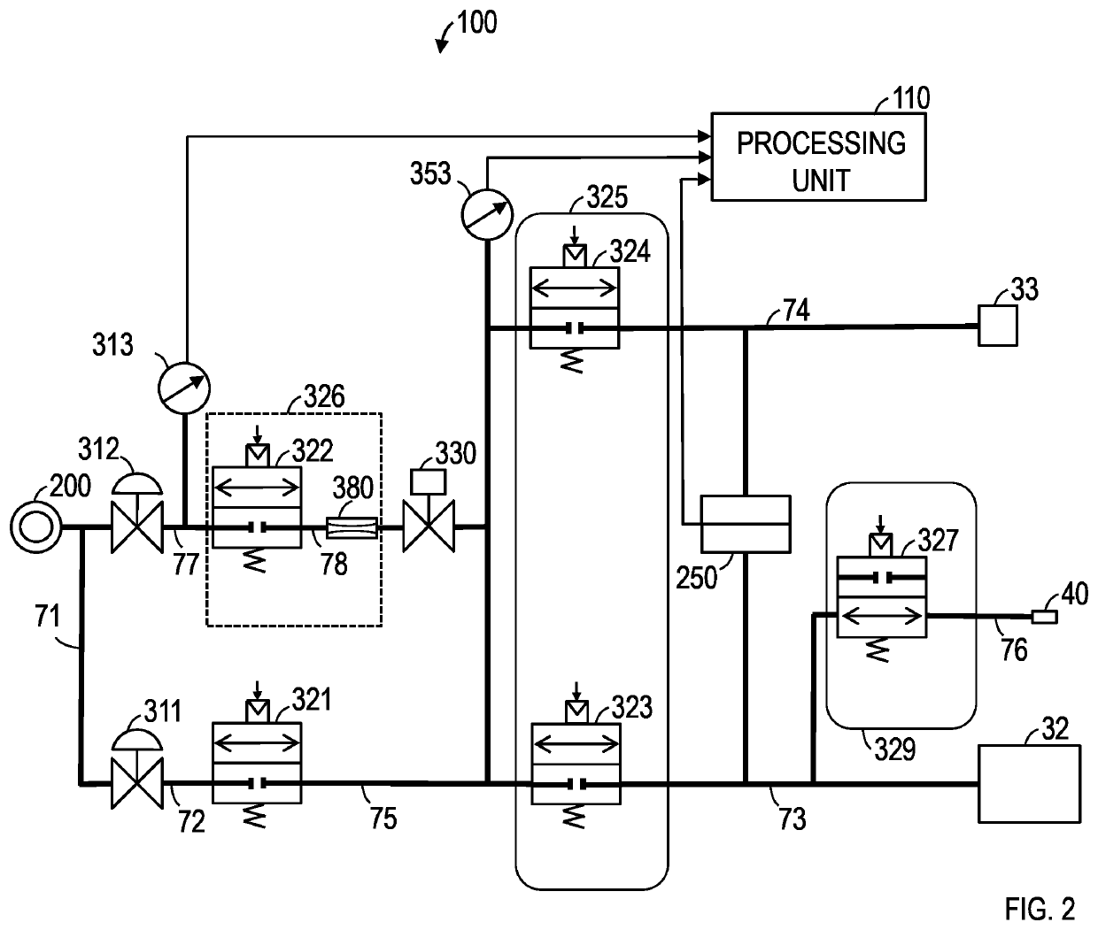
[0042]FIG. 2 shows an example of the functional configuration of a gas leak sensing device according to a first embodiment. A gas leak sensing device 100 includes a test pressure regulating valve 311, a primary pressure regulating valve 312, a primary pressure sensor 313, a test pressure sensor 353, a differential pressure sensor 250, a constant flow rate control valve 326, a pressurization control valve 321, an equal pressure valve 325, an exhaust valve 329, a source gas circuit 71, a pressurized gas circuit 72, a workpiece-side gas circuit 73, a master-side gas circuit 74, a supply-side gas circuit 75, an exhaust gas circuit 76, a primary pressure gas circuit 77, a silencer 40, and a processing unit 110. The source gas circuit 71, the pressurized gas circuit 72, the workpiece-side gas circuit 73, the master-side gas circuit 74, the supply-side gas circuit 75, the exhaust gas circuit 76, and the primary pressure gas circuit 77 can be metal tubes.

[0043]The source gas circuit 7...


PUM


Abstract

A gas leak sensing device includes a constant flow rate control valve, a pressurization control valve, a supply-side gas circuit, a master-side gas circuit, a workpiece-side gas circuit, an equal pressure valve, an exhaust valve, a test pressure sensor, and a differential pressure sensor. The supply-side gas circuit is connected with the constant flow rate control valve and the pressurization control valve. The equal pressure valve performs opening and closing between the supply-side gas circuit and the master-side gas circuit and opening and closing between the supply-side gas circuit and the workpiece-side gas circuit. The exhaust valve performs opening and closing between the workpiece-side gas circuit and outside. The test pressure sensor detects pressure in the supply-side gas circuit. The differential pressure sensor detects a differential pressure between the master-side gas circuit and the workpiece-side gas circuit.

Description

TECHNICAL FIELD[0001]The present invention relates to gas leak sensing devices for improving the reliability of gas leak sensing, setting methods for gas leak sensing, gas leak sensing methods, and tangible media.BACKGROUND ART[0002]Various gas leak sensing devices are known as instruments for checking whether there is leakage of gas from a workpiece under test or not by supplying pressurized gas to the workpiece under test (International Publication No. WO2014 / 184895 (hereinafter referred to as Patent Literature 1), and General Catalog, Cosmo Instruments Co. Ltd., [searched on Aug. 28, 2020], or the internet <https: / / www.cosmo-k.co.jp / document-download / >). Referring to FIG. 1, an outline of a gas leak sensing device 900 is described. Although the type of gas for use is not limited, the gas is air in this example. Accordingly, the designation “air leak sensing device” is appropriate. However, the designation “gas leak sensing device” is used in order not to lose generality.[00...

Claims


Application Information

Patent Timeline
Patent Type & Authority Applications(United States)
IPC IPC(8): G01M3/32G01F5/00
CPCG01M3/3263G01F5/005G01M3/26
Inventor FURUSE, AKIOSASAKI, SATORU
Owner COSMO INSTR
Why Eureka
Try Eureka