
Hanheld Electric Hair Dryer

a technology of electric hair dryer and hand held, which is applied in the direction of hair cleaning, hair drying, hair equipment, etc., can solve the problems of air noise and weakened airflow speed, and achieve the effects of accelerating heat dissipation efficiency, reducing negative pressure, and improving energy utilization efficiency

Pending Publication Date: 2022-03-24
GUANGZHOU OUSHENG TRADE CO LTD
View PDF0 Cites 0 Cited by
  • Summary
  • Abstract
  • Description
  • Claims
  • Application Information

AI Technical Summary

Benefits of technology

The present invention provides a handheld electric hair dryer that can provide high-pressure jet airflow while reducing negative pressure to achieve airflow balance, thereby improving energy utilization efficiency. The handheld hair dryer also accelerates heat dissipation efficiency while increasing airflow speed per unit area. The invention solves the problem of airflow disturbance and noise caused by insufficient replenishment of air fluid at the front of the fan unit. The supplementary air fluid is increased to reduce negative pressure and airflow disturbance, ultimately reducing air noise.

Problems solved by technology

On one hand, the airflow speed is weakened; on the other hand, the disturbance of the airflow and the lateral friction produce a large amount of air noise.

Method used


Image

  • Hanheld Electric Hair Dryer
  • Hanheld Electric Hair Dryer
  • Hanheld Electric Hair Dryer

Examples


example 1

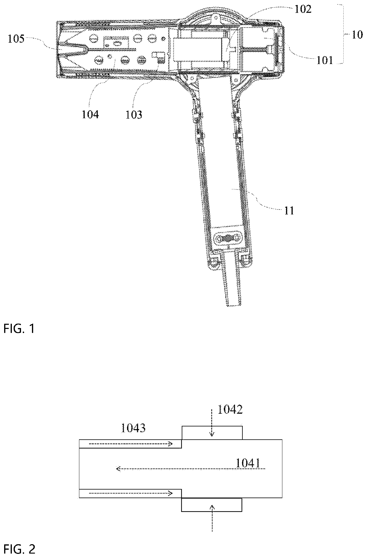
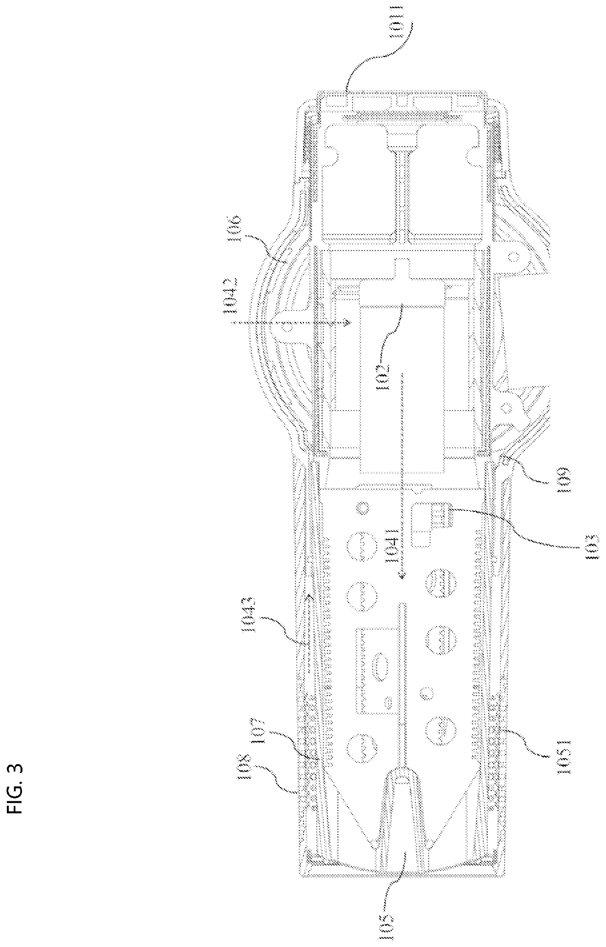
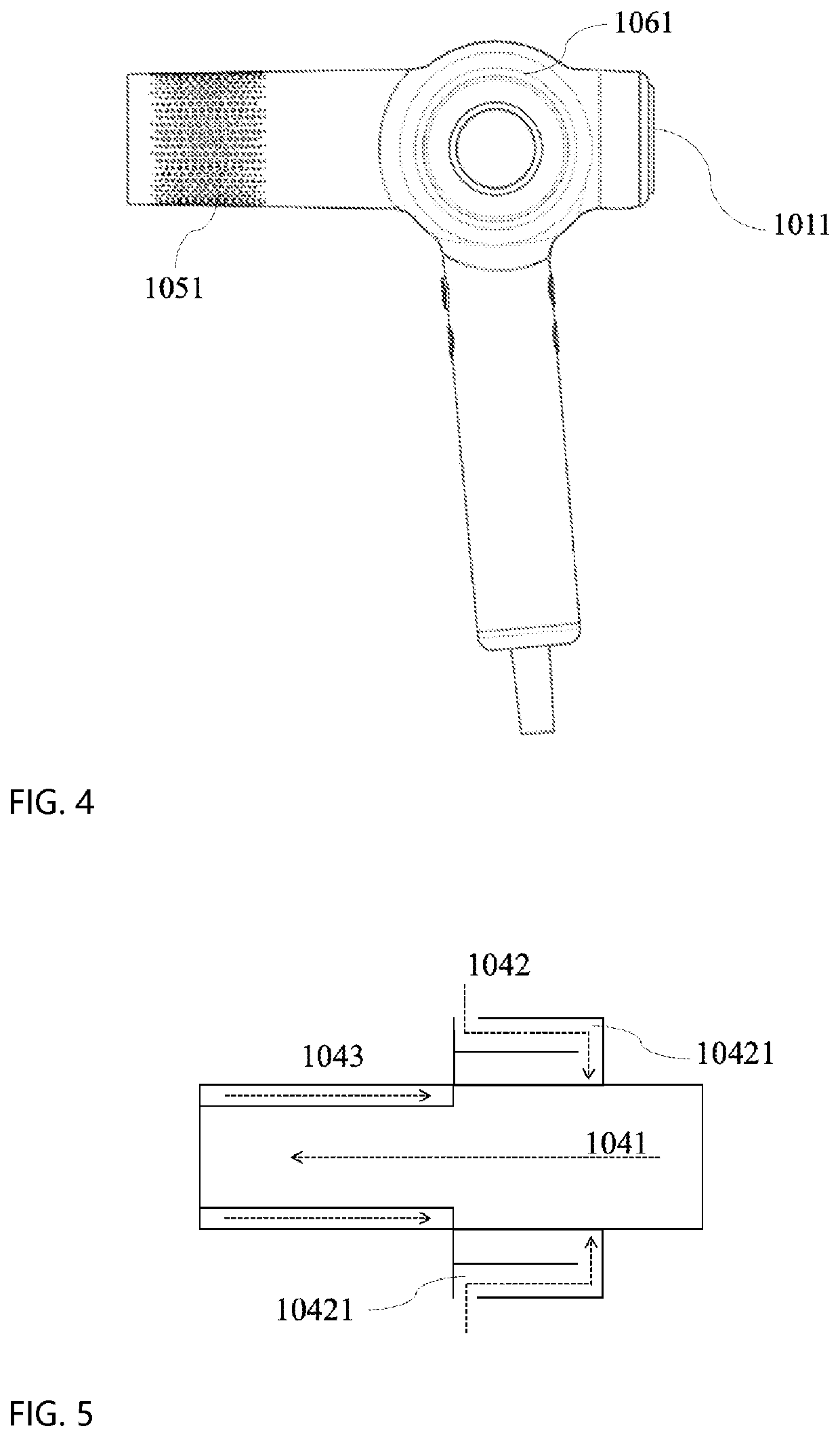
[0033]First, with reference to FIGS. 1-4, the handheld hair dryer according to the first embodiment of the present invention will be described. One technical solution adopted by the present invention is to provide a handheld hair dryer, as shown in FIG. 1, which comprises a main body 10 and a handle 11. The main body 10 comprises a primary fluid inlet 101, a fan unit 102, a heating element 103, a fluid flow path 104, and the primary fluid outlet 105. As shown in FIG. 2 (the direction of the arrow indicates the direction of fluid flow), the fluid flow path 104 comprises a primary fluid flow path 1041 that extends linearly from the primary fluid inlet 101 into the main body 10 to the primary fluid outlet 105. The side fluid flow path 1042 and the wall-defined fluid flow path 1043 are also shown in FIG. 2. The fluid sucked by the lateral path 1042 and the wall-defined fluid flow path 1043 enters the fan unit 102 through the primary fluid flow path 1041. The fan unit 102 is disposed on ...

example 2

[0043]Please refer to FIG. 5, which is a schematic diagram of a fluid flow path 104 of Embodiment 2 of the present invention. Only the differences between Embodiment 2 and Embodiment 1 will be described below, and the similarities will not be repeated here.

[0044]As shown in FIG. 5, the side fluid flow path 1042 comprises two bends 10421. The two bends 10421 are nearly right angles. The two bends 10421 are symmetrically disposed on the side fluid flow path 1042.

[0045]The setting of the two bends 10421 makes the cavity between the two bends 10421 have a natural frequency. When sound waves containing various frequency components enter the short pipe 107 connected to a third opening 1061 (as shown in FIG. 6), only sound waves of certain frequencies near the natural frequencies of the multiple holes of the third opening 1061 can pass through to reach the outlet of the third opening 1061. While sound waves of some frequencies cannot pass through the third opening 1061 and can only be refl...


PUM


Abstract

A handheld electric hair drier comprising a main body including a primary fluid inlet, a primary fluid outlet, a fan unit, a heating element, and a fluid flow path, and a handle. The fluid flow path comprises a primary fluid flow path that extends from the main body to the primary fluid outlet along a straight line, a side fluid flow path, and a wall-defined fluid flow path. Air fluid drawn through the side fluid flow path and the wall-defined path enters the fan unit through the primary fluid flow path. The fan unit is arranged on the primary fluid flow path, and the fan unit sucks fluid into the primary fluid flow path and transmits the fluid to pass through the heating element, so that the fluid in the primary fluid flow path is heated. The hair drier can provide high-pressure jet airflow and improve the air supplementing speed.

Description

CROSS REFERENCE TO RELATED APPLICATIONS[0001]This is a continuation-in-part application which takes priority from Chinese patent application no. 202011008242.7, filed on Sep. 23, 2020 (DAS code: 56AB), Chinese patent application no. 202011008298.2, filed on Sep. 23, 2020 (DAS code: 56AC), Chinese patent application no. 202011010666.7, filed on Sep. 23, 2020 (DAS code: 56EE) and Chinese patent application no. 202011010669.0 filed on Sep. 23, 2020 DAS code: 56AA.FIELD OF THE INVENTION[0002]The present invention relates to the field of handheld household appliances, in particular to a handheld electric hair dryer used for hair care and such as hair dryers and heat setting brushes.BACKGROUND OF THE INVENTION[0003]Based on the characteristics that the hair dryer can quickly shape and dry, it has a larger audience. The fan unit in the hair dryer can suck air from the air inlet of the hair dryer, and send the drawn air out from the air outlet that is opposite to the air inlet, so as to ach...

Claims


Application Information

Patent Timeline
IPC IPC(8): A45D20/12
CPCA45D20/124A45D20/12
Inventor CHEN, LIQUANZHANG, WEIDONG
Owner GUANGZHOU OUSHENG TRADE CO LTD
Learn More