
Cavity for a microwave oven

a cavity and microwave oven technology, applied in the field of cavity for cavity microwave ovens, can solve the problems of difficult to match the shape of the food container with the shape of the food container, the shape of the field is still not easy to predict or control, and the frequency of the cavity of the cavity of the cavity is not controlled precisely, so as to achieve uniform improve the distribution of heat in the food product, and improve the effect of heat distribution

Pending Publication Date: 2022-04-07
SOC DES PROD NESTLE SA
View PDF0 Cites 0 Cited by
  • Summary
  • Abstract
  • Description
  • Claims
  • Application Information

AI Technical Summary

Benefits of technology

The patent describes a microwave oven that uses a cavity to position or target the heating of a food product. This allows for more precise heating of specific areas of the food, such as a higher or lower heat capacity needed for different products. The cavity also minimizes edge overheating of the food and ensures the area around the cavity walls is not affected. The microwave oven also has a door for safety, protection from emitted microwaves and vapors. The technical effect is a more targeted and efficient heating of food with reduced energy consumption.

Problems solved by technology

In fact, there are several aspects of today's household microwave ovens and their interaction with food that can lead to unsatisfactory results: The vast majority of household microwave ovens have a magnetron as microwave source, because this device is inexpensive and delivers enough power for quick heating.
However, the frequency of microwaves from magnetrons is not controlled precisely and may vary between 2.4 and 2.5 GHz (for most household ovens).
Although Solid State Technology enables very defined and reproducible heating patterns, the shape of these patterns is still not easy to predict or control.
Moreover, the shapes of the fields tend to be very convoluted and hard to match with the shape of t food container.
However, targeted preferential heating, e.g. of one compartment in a food package with several compartments, is not desired and not possible.
A common problem is that the amount of energy supplied to each of the compartments does not meet the culinary requirements of the food therein.
Since all components need to reach a safe temperature, the vegetable portion is often overcooked.
As the fields are still unknown after scanning the cavity, there is a risk of wrong interpretation of the scanning results and failure to achieve the targeted uneven heating.

Method used


Image

  • Cavity for a microwave oven
  • Cavity for a microwave oven
  • Cavity for a microwave oven

Examples


Embodiment Construction

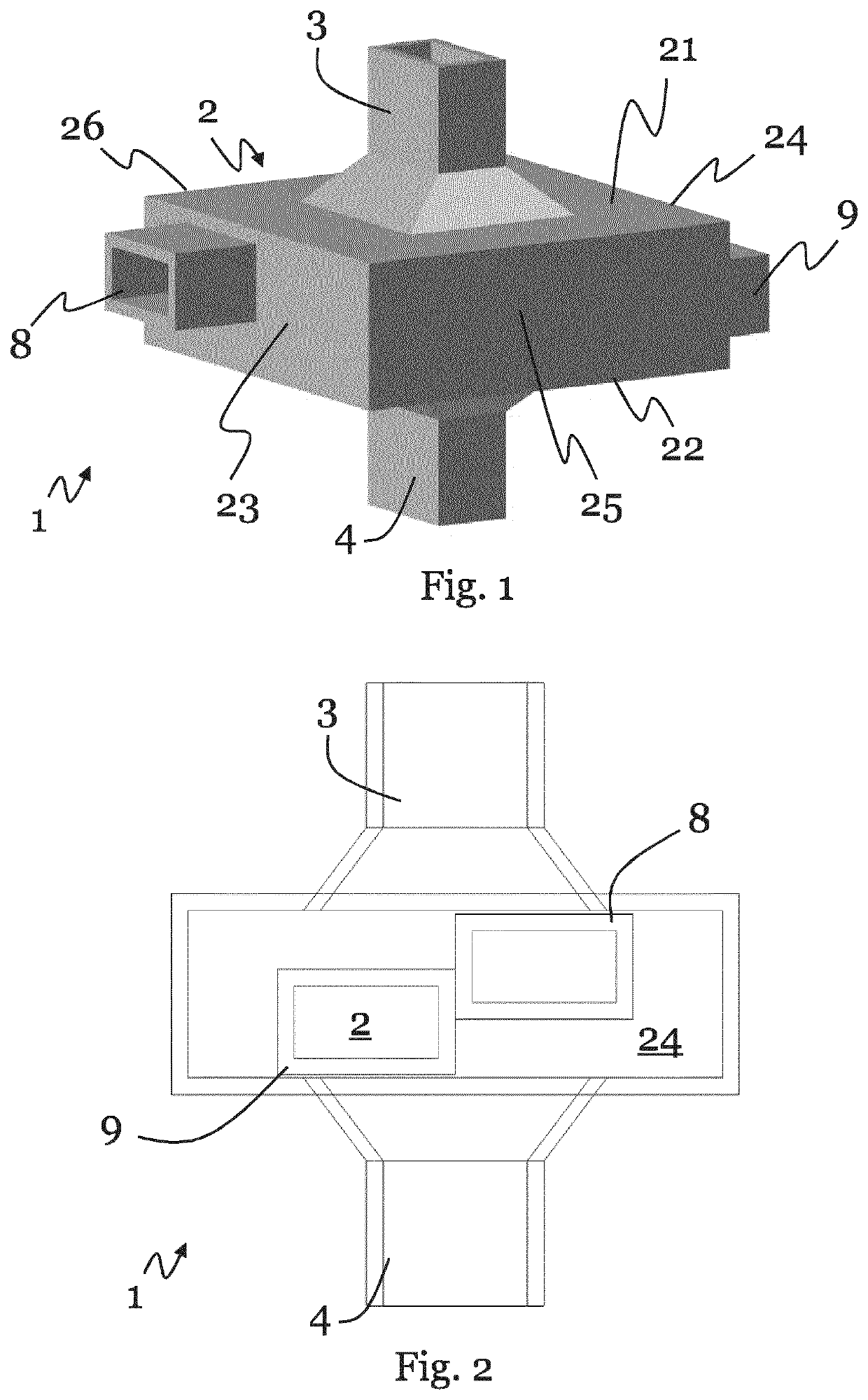
[0027]In the following, the invention is described exemplarily with reference to the enclosed figures, in which

[0028]FIG. 1 is a schematic perspective view of a cavity according to a preferred embodiment of the invention,

[0029]FIG. 2 is a schematic side view of the cavity shown in FIG. 1,

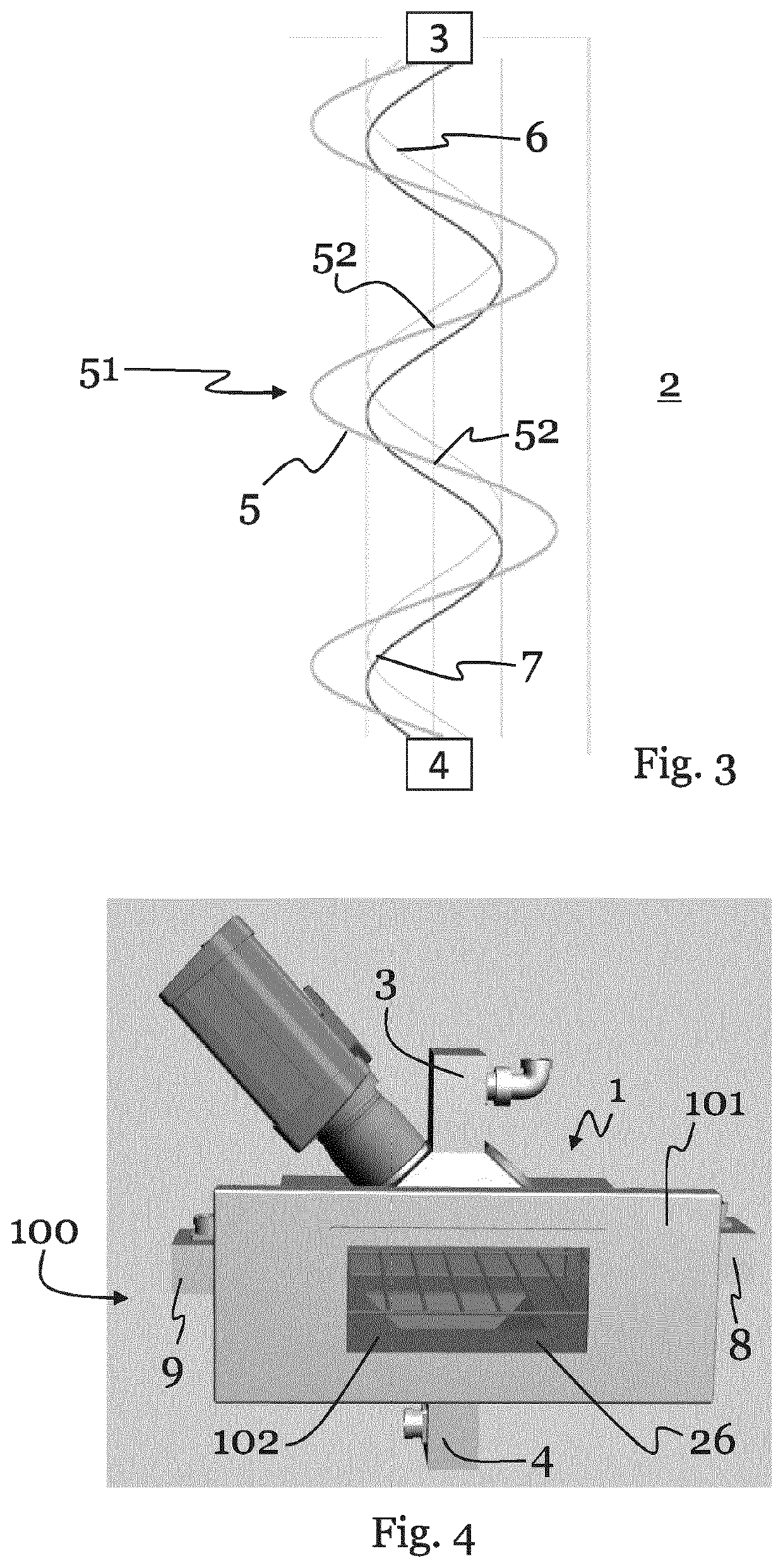
[0030]FIG. 3 schematically shows a standing microwave of a preferred embodiment of the cavity according to the invention,

[0031]FIG. 4 is a schematic perspective view of a microwave oven according to a preferred embodiment of the invention,

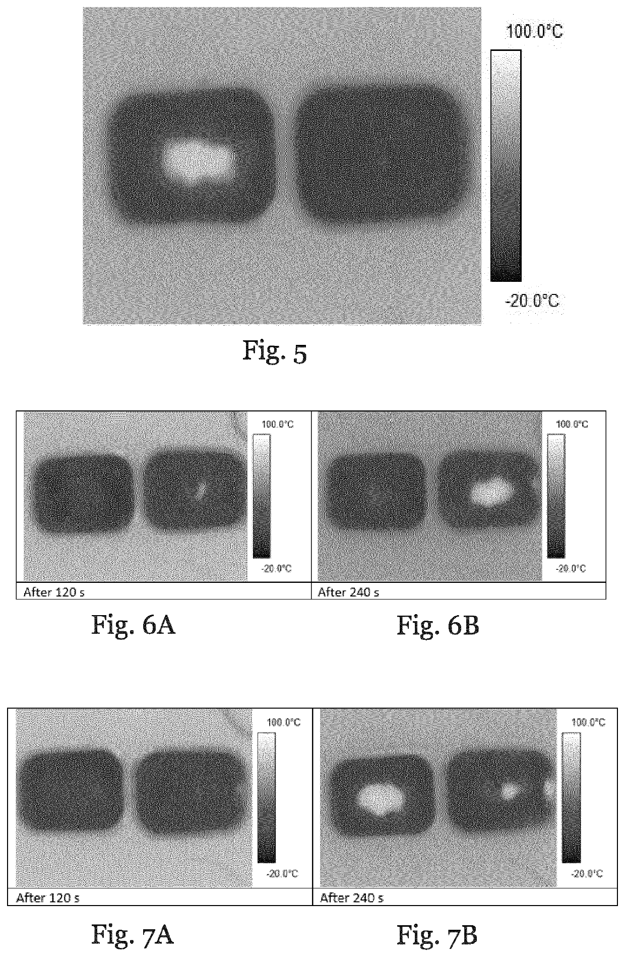
[0032]FIG. 5 is a schematic illustration of an infrared image of a first example, which was taken after the first example was heated by a cavity according to a preferred embodiment of the invention,

[0033]FIGS. 6A and 6B are schematic illustrations of an infrared image of a second example, which was heated by a cavity according to a preferred embodiment of the invention,

[0034]FIGS. 7A and 7B are schematic illustrations of infrared images of a third example, which wa...


PUM


Abstract

The invention relates to a cavity (i) for a microwave oven. The cavity (1) comprises: a space (2) for receiving ε food product, at least two solid state microwave sources for generating microwaves, a control unit for controlling the solid state microwave sources, and two microwave emitters (3, 4) for coupling the microwaves (6, 7) generated by the solic state microwave sources into the space (2). The control unit is configured to control the solid state microwave sources such that E standing microwave (5) for providing a zone (51) for heating E food product received by the space (2) is generated between the two microwave emitters (3, 4), and such that the position of the zone (51) with respect to the space (2) is adjustable based on the control. The inventor further relates to ε icrowave emitters 3, 4.

Description

1. FIELD OF THE INVENTION[0001]The invention relates to a cavity for a microwave oven, a microwave oven comprising such a cavity, and t method for heating a food product.2. TECHNICAL BACKGROUND[0002]In the prior art, microwave ovens are very common appliances with more than 90% household penetration in the US and comparable numbers in other industrialized countries. Besides the re-heating of leftovers, the preparation of frozen meals and snacks is considered to be the most important use of microwave ovens. The main benefit of microwave ovens is their speed, which is a result of the penetration of the electromagnetic waves into the food products. Although this heating mechanism is sometimes called ‘volumetric heating’, it is important to know that the heating pattern is not very even throughout the volume of the food. In fact, there are several aspects of today's household microwave ovens and their interaction with food that can lead to unsatisfactory results: The vast majority of ho...

Claims


Application Information

Patent Timeline
IPC IPC(8): H05B6/68H05B6/72
CPCH05B6/686H05B6/72H05B6/6435H05B2206/044H05B6/687H05B6/70Y02B40/00
Inventor ERLE, ULRICH JOHANNES
Owner SOC DES PROD NESTLE SA
Learn More