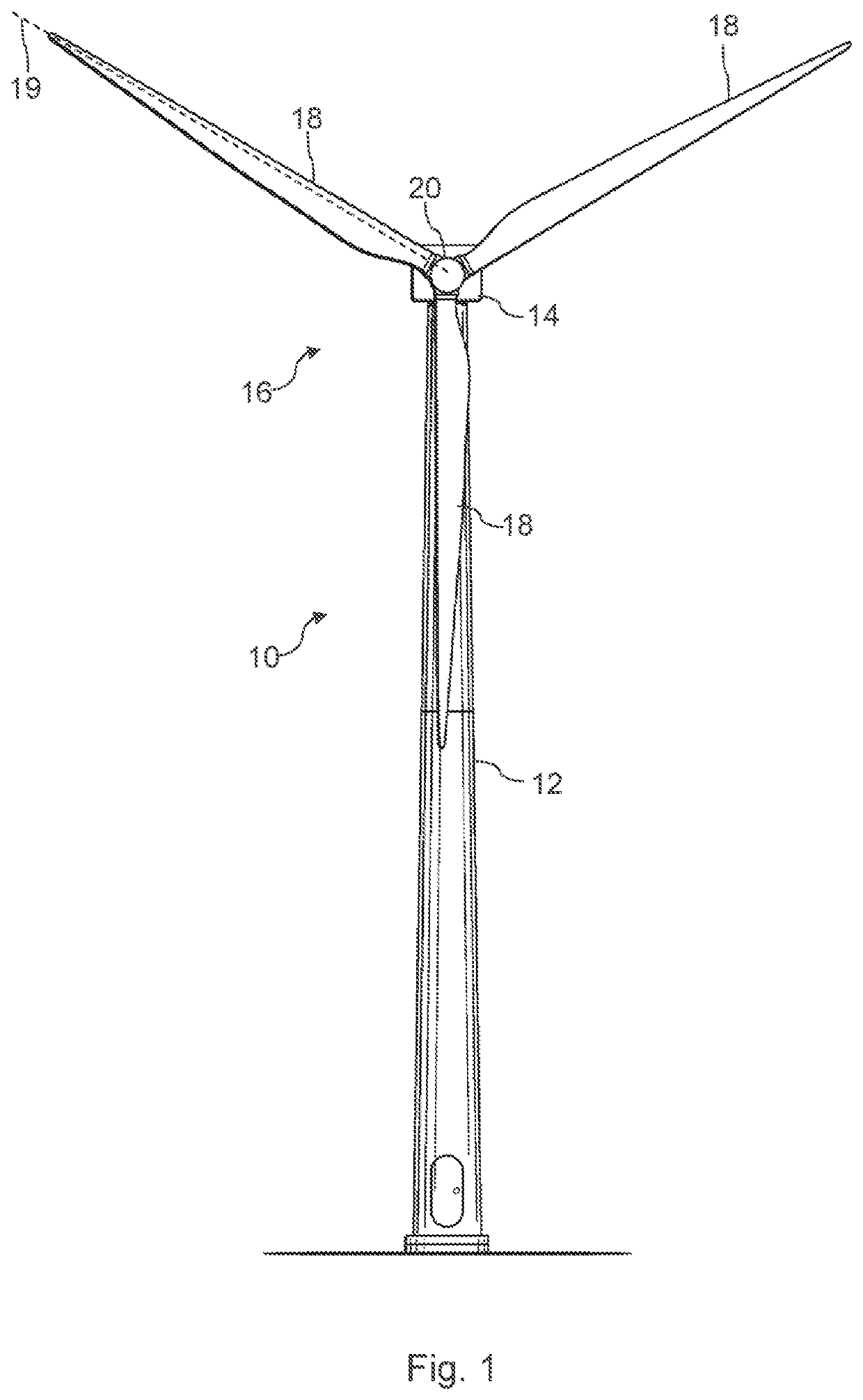
Control of side-side and fore-aft vibrational movement of a wind turbine
- Summary
- Abstract
- Description
- Claims
- Application Information
AI Technical Summary
Benefits of technology
Problems solved by technology
Method used
Image

Examples
first embodiment
[0087]In the first embodiment, shown in FIG. 8, the determination of side-side and fore-aft components of the vibrational movement of the tower 12 is based on a measurement of parameters of the wind turbine 10. It is envisaged that because this method 110 is based on instantaneous or short-term measurements, it will be performed locally within the wind turbine 10 by the control means 32, although it may alternatively or also be performed remotely by a park controller or control means shared by more than one wind turbines.
[0088]Where the side-side and fore-aft components are determined based on the measurements, the components are used to control the tower damping systems of the wind turbine 10 iteratively so that the fatigue loads experienced by the tower 12 are as substantially equal in the fore-aft and side-side directions. As will be elaborated on below, the short-term correction of tower loading ensures that the forces experienced by the tower 12 are as closely aligned with the ...
second embodiment
[0106]In the second embodiment, shown in FIG. 9, the determination of side-side and fore-aft components of the vibrational movement of the tower is based on estimated values. Utilising estimates enables a longer-term control protocol, where asymmetries in the fore-aft and side-side components are corrected over a longer period of time by adjusting the estimated components on which the control is based. Implementing changes in fore-aft and side-side components over a long period of time permits a slow rate of change of components so control of the turbine does not result in high, potentially harmful loads being exerted. It is envisaged that some of this embodiment method will be performed remotely by a park controller or control means shared by more than one turbine, while some of this embodiment will be performed locally, as will be explained.
[0107]In the method 130 of FIG. 9, the fore-aft and side-side components are determined, at steps 132, 134, based on estimated load values or ...
PUM
 Abstract
Description
Claims
Application Information
 - Generate Ideas
- Intellectual Property
- Life Sciences
- Materials
- Tech Scout
- Unparalleled Data Quality
- Higher Quality Content
- 60% Fewer Hallucinations
Browse by: Latest US Patents, China's latest patents, Technical Efficacy Thesaurus, Application Domain, Technology Topic, Popular Technical Reports.
© 2025 PatSnap. All rights reserved.Legal|Privacy policy|Modern Slavery Act Transparency Statement|Sitemap|About US| Contact US: help@patsnap.com