

Sunshade for Outdoor Public Space and Outdoor Public Space Having Such a Sunshade
a technology for outdoor public spaces and sunshade, applied in the field of sunshade, can solve problems such as inconvenience or danger, and achieve the effect of improving the situation
- Summary
- Abstract
- Description
- Claims
- Application Information
AI Technical Summary
Benefits of technology
Problems solved by technology
Method used
Image

Examples
second embodiment
[0119]In still another example pivotal mount 7a may include a motorized mechanism as will be explained below with regard to the
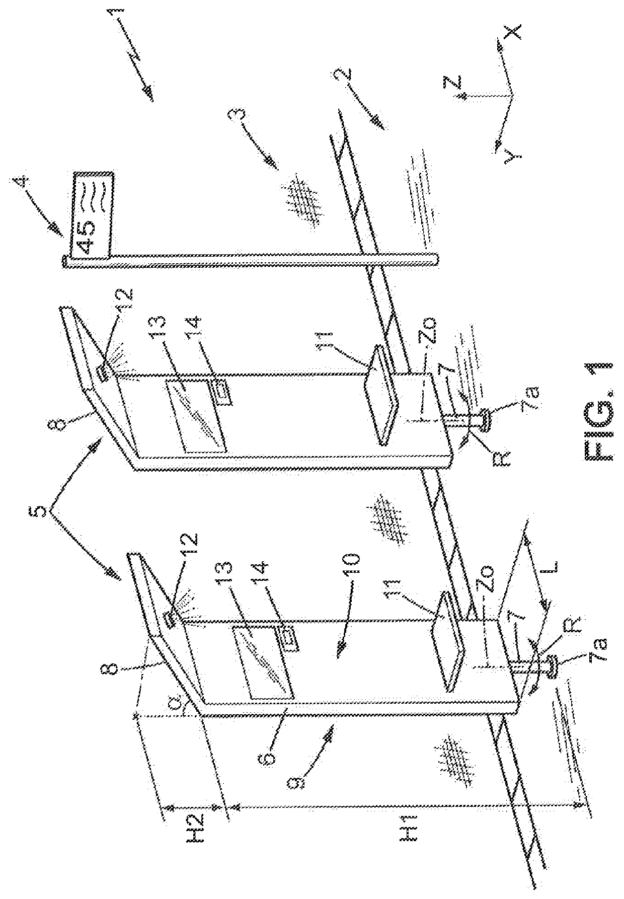
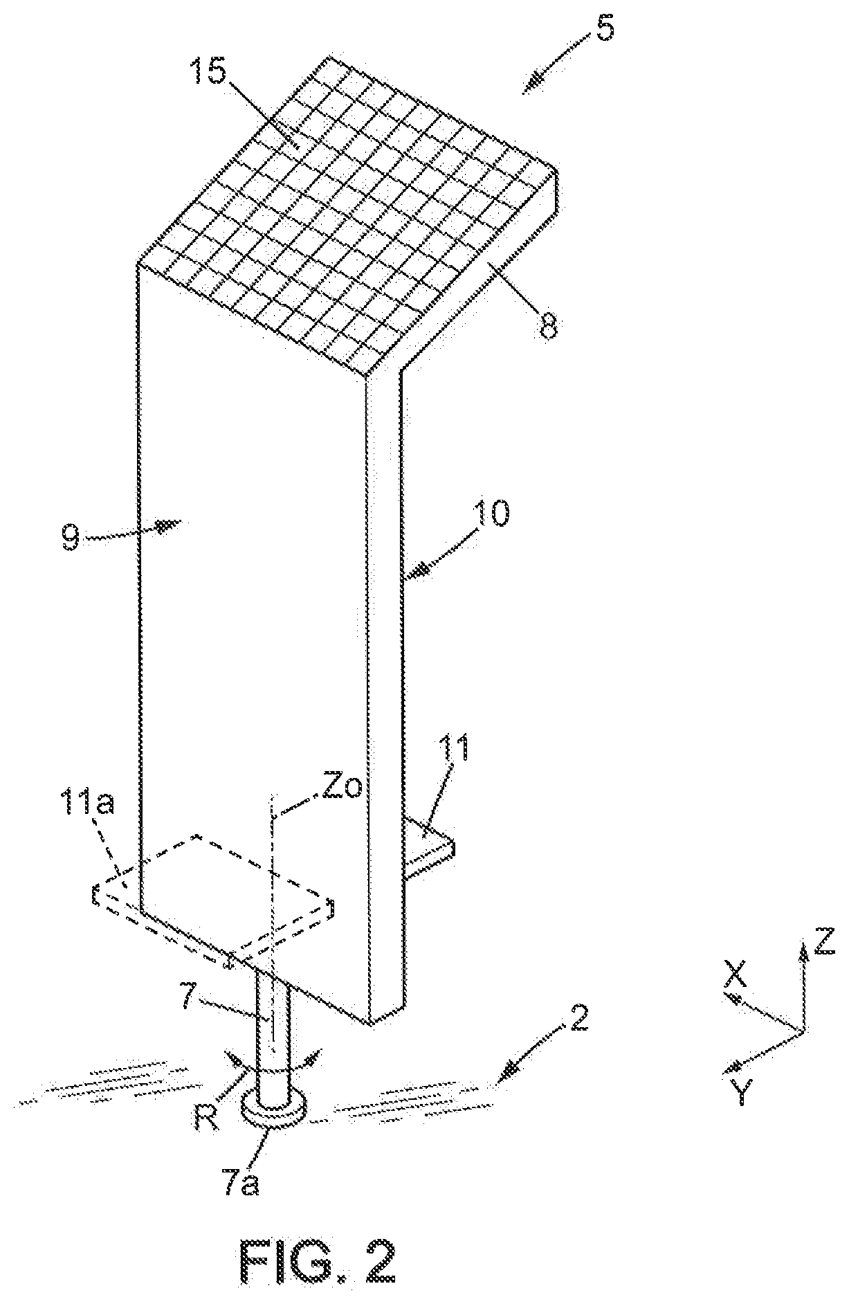
[0120]Pane 6 is of substantially flat and elongate shape, extending longitudinally, substantially parallel to a vertical axis Z, between a lower end connected to the pivotal mount and an upper end.
[0121]The upper end of pane 6 is a free end in the example disclosed in the drawings.
[0122]Said upper end of said pane may be at a height H1 comprised between 130 cm and 300 cm above the ground. The lower values of this range are usable especially when the pane is equipped with a seat as will be explained below. In one example of preferred embodiment, said height H1 may be comprised between 180 cm and 250 cm. For instance, height H1 may be of about 210 cm.
[0123]The lower end of pane 6 may be at a height of a few tens of centimeters above the ground, for instance 20 to 50 cm, which helps limit the obstruction by sunshade 1 of the sidewalk.
[0124]Pane 6 also extends l...
fifth embodiment
[0159]In the fifth embodiment, shown in FIGS. 8-10, said rotation control apparatus is adapted to limit a rotation amplitude of the pane 6 around the rotation axis Z0. The rotation amplitude may be here limited to about 340 degrees, but of course the rotation amplitude could be limited to a different value.
[0160]More specifically, the rotation amplitude can be limited by abutment of at least one stop member 28 which is unitary with pane 6, against at least one fixed counter-stop member 29.
[0161]In the example shown in FIGS. 8-10, the sunshade 5 has one stop member 28 and one counter-stop member 29.
[0162]In the fifth embodiment, pivotal mount 7a may include a basis 23, a seat 24 and a bearing 25 interposed between basis 23 and seat 24. Basis 23 may be superposed on bearing 25 which is superposed on seat 24. Basis 23 may be unitary with foot 7 and pane 6, while seat 24 may be fixed to the ground, e.g. to the sidewalk 2.
[0163]Stop member 28 may be part of basis 23 and counter-stop memb...
sixth embodiment
[0169]In the sixth embodiment, shown in FIGS. 11-18, said rotation control apparatus may comprise:[0170]a braking system, e.g. a permanent braking system;[0171]a rotation limitation system;[0172]a seat-activated immobilization device which is activated when a user is seated on the seat of the sunshade;[0173]a user-controlled immobilization device which is normally maintained activated and can be deactivated by an actuator controlled by a user;[0174]a return system adapted to return the pane 6 in a predetermined rest position.
[0175]Each of these five features could be used alone or in combination with one or more of the other five above features.
[0176]The braking system is adapted to apply a braking torque on pane 6 comprised between 1 and 15 Nm. In other words, it is necessary to apply a torque of more than said braking torque on pane 6 to rotate it around the axis of rotation Z0.
[0177]The braking system may include at least one braking device 33, 33a (see FIGS. 15-16)...
PUM
 Abstract
Description
Claims
Application Information