
Monitoring system for pump with mechanical seal lubrication arrangement

a technology of mechanical seals and monitoring systems, which is applied in the direction of machines/engines, liquid fuel engines, and positive displacement liquid engines, etc., can solve the problems of significant downtime, seal failure, and cascading failure of other parts of the pump

Active Publication Date: 2022-04-28
CORNELL PUMP CO LLC
View PDF13 Cites 1 Cited by
  • Summary
  • Abstract
  • Description
  • Claims
  • Application Information

AI Technical Summary

Benefits of technology

The patent describes a system and method for monitoring the level of lubricating fluid in a pump's seal lubrication system. This is done through an integrated system that includes a level sensor and a monitoring device or an industrial internet-of-things device. The monitoring device allows pump users to remotely monitor the level of the fluid in the reservoir, and can also automatically shut down the pump equipment when low lubrication reservoir levels are detected. The technical effect of this system is that it allows for more efficient monitoring of seal lubrication without the need for a person to physically present at the pump site.

Problems solved by technology

When these seals are damaged, repair / replacement of the seals can cause significant down time, since accessing the seals is labor-intensive and typically requires disassembling the pump.
When there is no lubricating fluid on the mechanical seals, heat from friction can quickly cause damage to the seal materials, leading to seal failure.
A seal failure can quickly lead to cascading failures in other parts of the pump, such as intrusion of pumped fluids into the pump bearings.

Method used


Image

  • Monitoring system for pump with mechanical seal lubrication arrangement
  • Monitoring system for pump with mechanical seal lubrication arrangement
  • Monitoring system for pump with mechanical seal lubrication arrangement

Examples


Embodiment Construction

[0013]The following detailed description refers to the accompanying drawings. The same reference numbers in different drawings may identify the same or similar elements. Also, the following detailed description does not limit the invention.

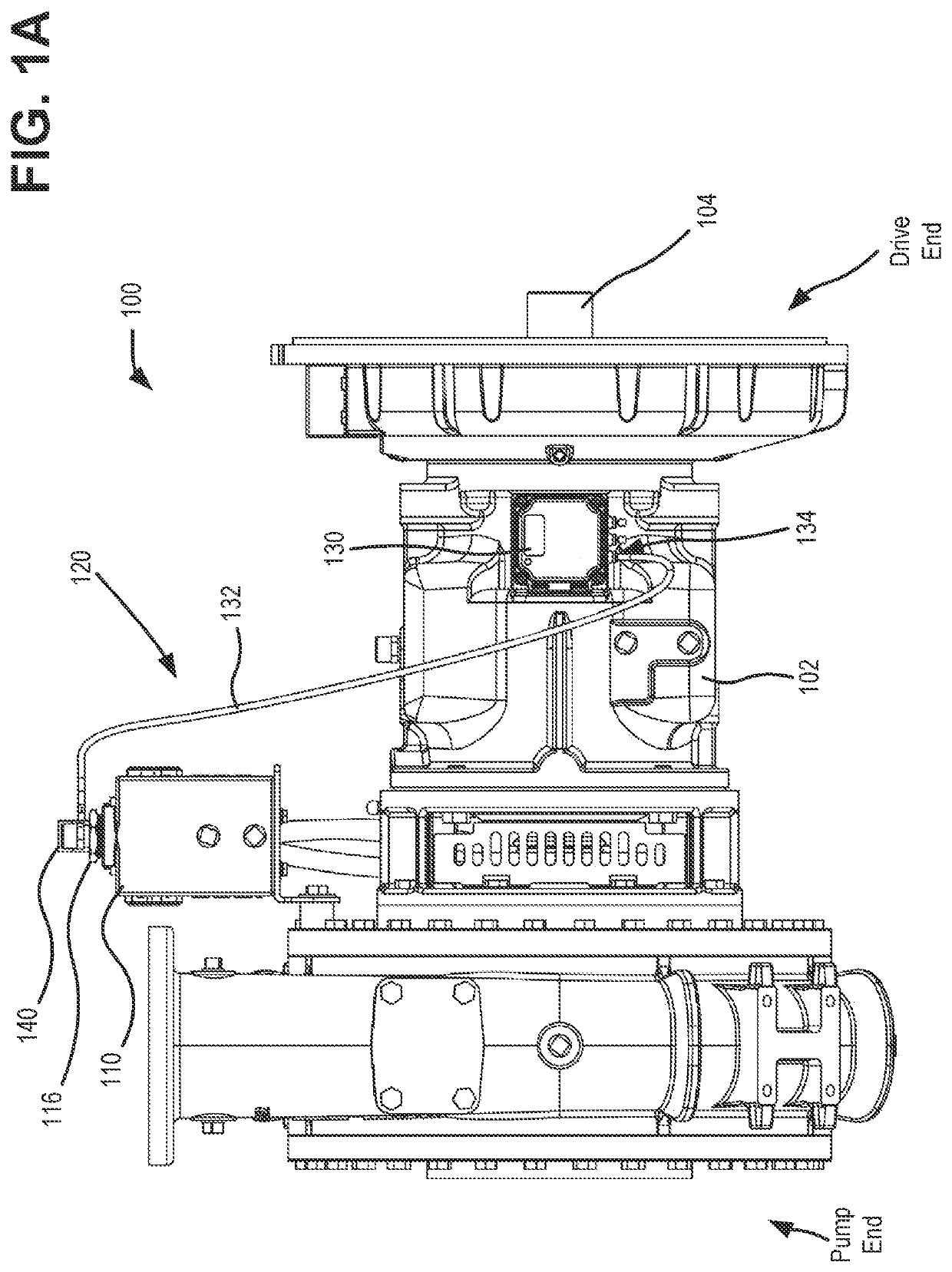
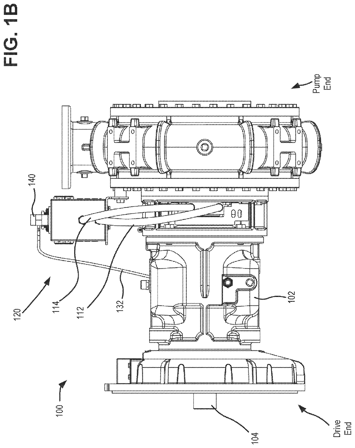
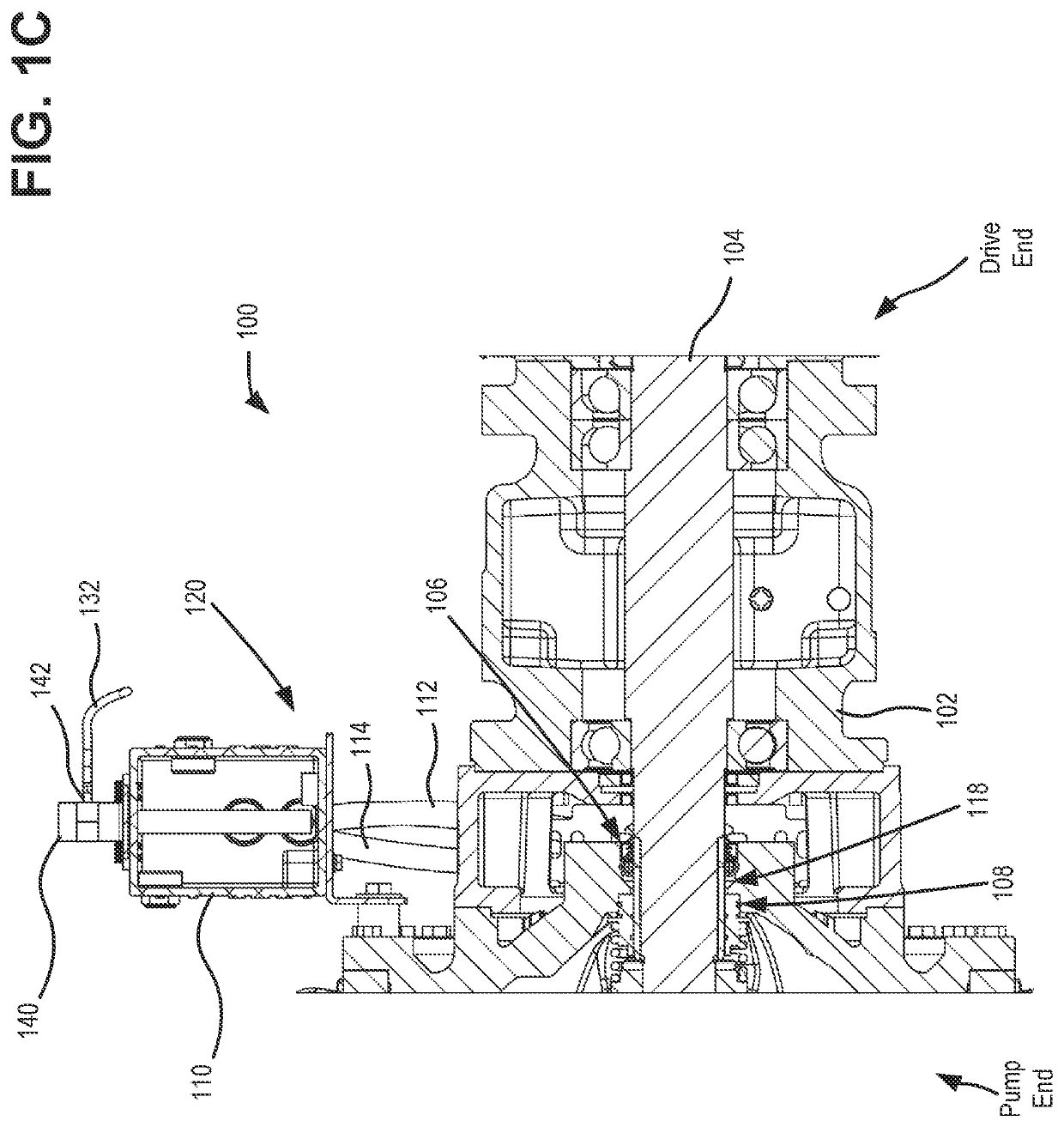
[0014]An industrial pump system may include a reservoir that is filled with a lubricating fluid (e.g., water, a light oil, a water / propylene glycol mix, etc.), which is used to lubricate mechanical seal faces on the pump shaft in the event the pump is run “dry” (e.g., without any pumped liquid running though the pump). The reservoir is connected to the pump by a set of hoses which allows the fluid to flow from the reservoir through openings in the pump housing and onto the seal faces.

[0015]Fluid level changes in the lubrication reservoir can be evidence of seal leak or another problem with the seal lubrication system. Examples of situations when the level of the fluid in the reservoir can drop include: (1) fluid in the reservoir decreases over tim...


PUM


Abstract

Systems and methods are provided for remotely monitoring liquid lubricant levels for pump equipment. A system includes a reservoir to store lubricant and a lubrication gland to expose a shaft seal of the pump equipment to the lubricant. A feed line and a return line circulate the lubricant between the reservoir and the lubrication gland. A level sensor is configured to measure a fluid level in the reservoir. The level sensor uses a communication interface to transmit fluid level data a monitoring device mounted to the pump equipment. The monitoring device is configured to compare the fluid level data against stored alert thresholds and send, to a provider network, an alert signal when the fluid level data is below an alert threshold. If the fluid level data is not below an alert threshold, the monitoring device stores the fluid level data for periodic reporting.

Description

CROSS-REFERENCE TO RELATED APPLICATION[0001]This application claims priority to under 35 U.S.C. § 119, based on U.S. Provisional Patent Application No. 63 / 104,800 filed Oct. 23, 2020, titled “Monitoring System for Pump with Mechanical Seal Lubrication Arrangement,” the disclosure of which is hereby incorporated by reference.BACKGROUND OF THE INVENTION[0002]Industrial pumps may use seals to prevent leakage, particularly at locations where a rotating shaft passes through a stationary housing. When these seals are damaged, repair / replacement of the seals can cause significant down time, since accessing the seals is labor-intensive and typically requires disassembling the pump. A common failure mechanism for seals is running the pump dry (e.g., without pumping fluid). When there is no lubricating fluid on the mechanical seals, heat from friction can quickly cause damage to the seal materials, leading to seal failure. A seal failure can quickly lead to cascading failures in other parts o...

Claims


Application Information

Patent Timeline
IPC IPC(8): F01M11/12F01M11/04F01M11/02F16N29/02F16N19/00
CPCF01M11/12F01M11/0458F01M11/02F16N29/02F16N2210/16F01M2011/021F01M2011/0466F16N2250/18F16N19/006F04B53/18F04D29/061F04D29/128F04D15/0088F04D15/0218F16N7/02F16N7/36F16N19/003F16N29/04F16N2210/14F16N2260/04F16N2260/16F16N7/00F16N29/00F16J15/162F04B49/02F04B49/10
Inventor O'CALLAGHAN, COLINAMSTAD, LUKEWARREN, WILLIAM JAMESLINDEMAN, ADAMENTERLINE, ANDREW
Owner CORNELL PUMP CO LLC
Learn More