Resistance multi purpose welder attachment

a multi-purpose, welder technology, applied in the direction of resistance electrode holders, electrode features, manufacturing tools, etc., can solve the problems of x-type configuration offering less flexibility in tooling, various limitations of spot welding related art, etc., to achieve accurate measurements of compression and width or thickness of metal placed

Active Publication Date: 2022-05-05
OLSSON JORAN
View PDF6 Cites 0 Cited by
  • Summary
  • Abstract
  • Description
  • Claims
  • Application Information

AI Technical Summary

Benefits of technology

[0011]The utility of such a wider initial opening of the device herein, is enabled by a novel engagement of the two supports for the electrodes forming a weld, in a sliding pivoting engagement which allows for movement of opposing electrodes toward each other, which allows for a wider opening as in an X-type spot welding device. However, the two electrodes upon contact with the opposing sides of the metal to be welded, does so in a collinear fashion of a C-type welder. This configuration provides the user with the utility of both the X and C type welders.
[0016]It is this sliding on the bushing within the diagonal slot, formed in the end of the first arm, that allows the device to achieve an open position similar to that of an X-type welder, and to translate to a closed position in a manner of a C-type welder. Thus, the user has the utility of a extra wide opening during engagement over metal to be spot welded. Subsequent movement of the first arm will then move along a path ending in a direct coaxial or aligned positioning. This positions the first electrode in alignment with the second electrode during operation to translate the first electrode toward the second electrode to form a sandwiched engagement with metal to be welded therebetween.
[0018]Currently, a length of the bushing from curved end to curved end L2, is 40-60 percent of the length L1 of the elongated slot from curved sidewall to curved sidewall. A current especially preferred mode of the device in the operative configuration herein has the length of the bushing L2, at 52-57 percent of the length of the slot L1. This configuration has been found in experimentation to provide for both a sliding and a rotation of the pivot, during opening and closing of the first arm and second arm to achieve the wide separation of the first and second electrodes.
[0021]An additional advantage of the disclosed device, having the translating rotating engagement between the first arm and the second arm at a pivot point, is the maintaining of a geometry between the components. As disclosed this translating and pivoting connection, maintains a 1:1 linear translation of the two electrodes toward each other. The disclosed connection also maintains a 1:1 force ratio of the contact between the first electrode with the second electrode during welding, relative to both the linear translation and the force “F” imparted by the operatively engaged translating welding electrode.
[0023]Further, because the linear movement of the driving actuator translating the welding electrode which rotates the first arm is at a 1:1 ratio relative to the linear movement of the first electrode toward the second electrode with both aligned. This allows for very accurate measurements of a width or thickness of metal placed therebetween. It additionally provides for extremely accurate measurements of compression thereof once placed therebetween. Thus, once the distance between the first and second electrode, when aligned and touching is zeroed or measured for zero, a subsequent linear movement by the driving actuator translating the welding electrodes can measure both the thickness of metal placed between the two first and second electrodes, and any collapse or compaction thereof during welding or continued force to compress the metal.

Problems solved by technology

However, this X-type configuration offers less flexibility in terms of tooling, because the paths of the two opposing and moving electrodes are not collinear.
Various limitations of the related art in spot welding will become apparent to those skilled in the art upon a reading and understanding of the specification below and the accompanying drawings.

Method used


Image

  • Resistance multi purpose welder attachment
  • Resistance multi purpose welder attachment
  • Resistance multi purpose welder attachment

Examples


Embodiment Construction

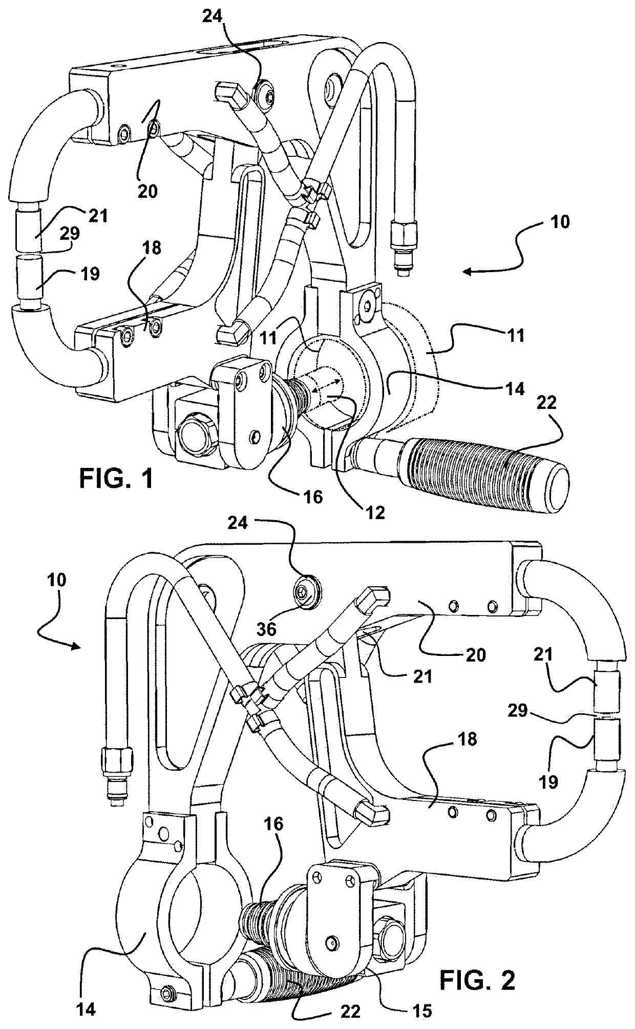
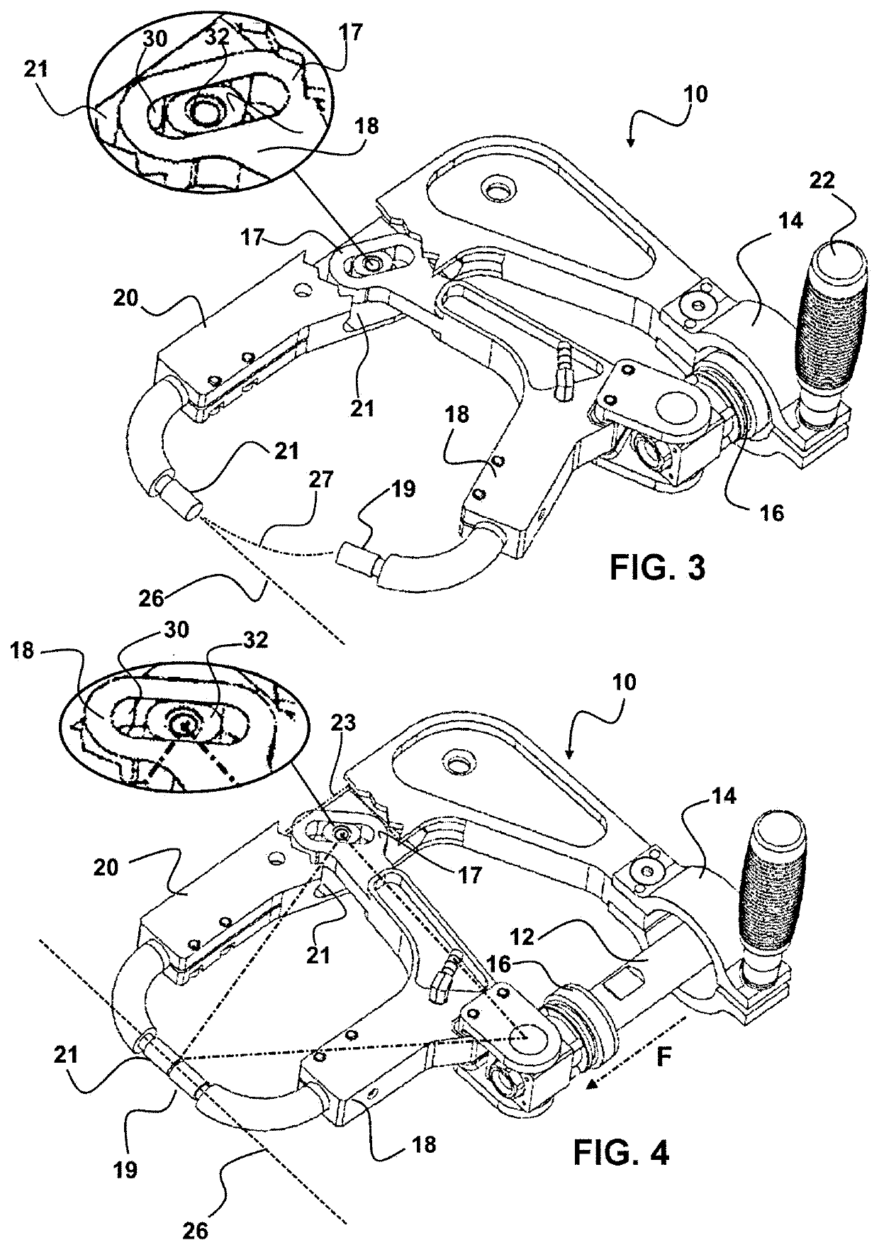
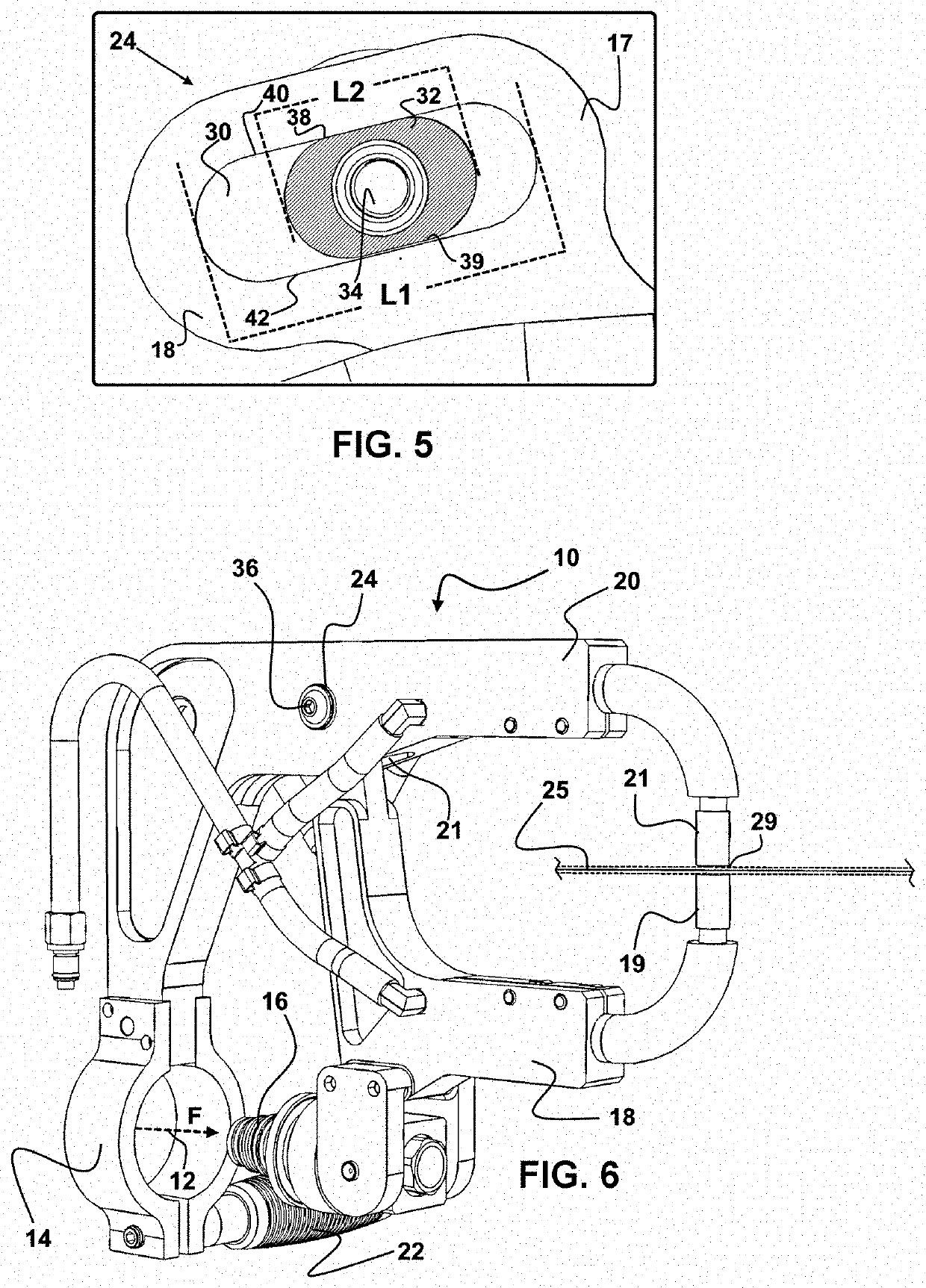
[0037]Referring now to the drawings of FIGS. 1-7, wherein similar parts of the invention are identified by like reference numerals. There is seen in FIGS. 1-2, the device 10 which is a portable resistance welder multi-purpose attachment device 10, which is configured for a removable fixed engagement to a hand held or similar welder 11 which has a translating welder electrode 12 in communication with electric current for welding. Such welders with translating welder electrodes 12 are well known and widely employed, such as for example and in no way limiting, the PS-500 or the I4S spot welder from ProSpot quality welding systems of Carlsbad, Calif.

[0038]Such handheld welders conventionally have a powered translating electrode 12 which is powered to move forward and reverse by hydraulic pressure, pneumatic pressure, or an electric drive such as for example a motor and worm gear. The term handheld welder 11 thus as used herein, means any welder which has controllable translating electro...


PUM

PropertyMeasurementUnit
slot angleaaaaaaaaaa
axis angleaaaaaaaaaa
angleaaaaaaaaaa

Abstract

A resistance welding device is configured for use in combination with a resistance welder having a translating welding electrode. A first arm of the welding device is in a translating rotational engagement with a second arm thereof. The first arm of the device is engageable to a translating electrode from the resistance welder. Translation of the welding electrode of the resistance welder moves first and second electrodes to contact metal therebetween and spot weld the metal.

Description

[0001]This application claims priority to U.S. Provisional Patent Application Ser. No. 62 / 858,237 filed on Jun. 6, 2019, which is included herein in its entirety by this reference thereto.FIELD OF THE INVENTION[0002]The disclosed device relates to the field of resistance welding more commonly known as spot welding. More particularly, this invention relates to a spot welding device which compresses and welds adjacent metal layers which are sandwiched between two electrodes at a compression point by a force communicated from a translating powered welder electrode. The force imparted by the two electrodes at the compression point of the device herein is substantially equal to the force communicated by the powered welder electrode. Fluid cooling provides a means to cool the electrodes during operation.BACKGROUND OF THE INVENTION[0003]Spot welding or resistance welding is a common manufacturing procedure of permanently engaging points upon two or more pieces of metal material through the...

Claims


Application Information

Patent Timeline
Patent Type & Authority Applications(United States)
IPC IPC(8): B23K11/11B23K11/30B23K11/28B23K11/31
CPCB23K11/115B23K11/314B23K11/28B23K11/3018
Inventor OLSSON, JORAN
Owner OLSSON JORAN
Why Eureka
Try Eureka