
Manufacturing process for elastomeric laminate

a manufacturing process and technology for elastomeric laminates, applied in the direction of layered products, chemistry apparatus and processes, other domestic articles, etc., can solve the problem of challenging process for elastomeric laminates which do not subsequently delaminate, and achieve superior properties and manufacturing processes

Active Publication Date: 2019-12-17
FIRST QUALITY BABY PROD
View PDF8 Cites 0 Cited by
  • Summary
  • Abstract
  • Description
  • Claims
  • Application Information

AI Technical Summary

Benefits of technology

The present invention is about a better way of making elastic material used in things like absorbent products. The method involves laminating layers of non-woven fabric to an elastic film using a special adhesive. The non-woven fabric is then heated and stretched while it is still attached to the elastic film. This results in an elastic material that has better properties than traditional methods.

Problems solved by technology

Manufacture of elastomeric laminates which do not subsequently delaminate is a challenging process.

Method used


Image

  • Manufacturing process for elastomeric laminate
  • Manufacturing process for elastomeric laminate
  • Manufacturing process for elastomeric laminate

Examples


example 1

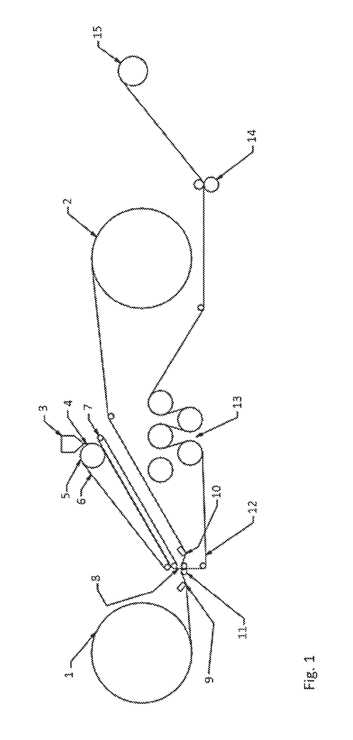
[0057]In a two-step manufacturing process for an elastomeric laminate, the following process was used. Two nonwoven rolls (NW BiCo material) were unwound and one fed to each side of an extruded melted polymer (Kraton G1643MS, from Kraton Polymers US, Houston, Tex.). The extruded melted polymer has been fed as a film from a die and deposited onto a conveyor belt. The drive roll was chilled and the polymer film was conveyed by two transfer belts. At a combining / nip area, each of the two nonwoven facings were fed into contact with coating applicator. The coating applicator was a hot melt slot coating applicator. Above the nip, the elastic film was fed by the conveyor belts. The hot melt adhesive was applied to the two nonwovens prior to lamination. Exemplary patterns include lines across the width, 0.85 mm wide, 2 mm center distance. The laminated web resulting from this was fed through rollers that were chilled as necessary. The laminated web was optionally slit at this point, but was...

example 2

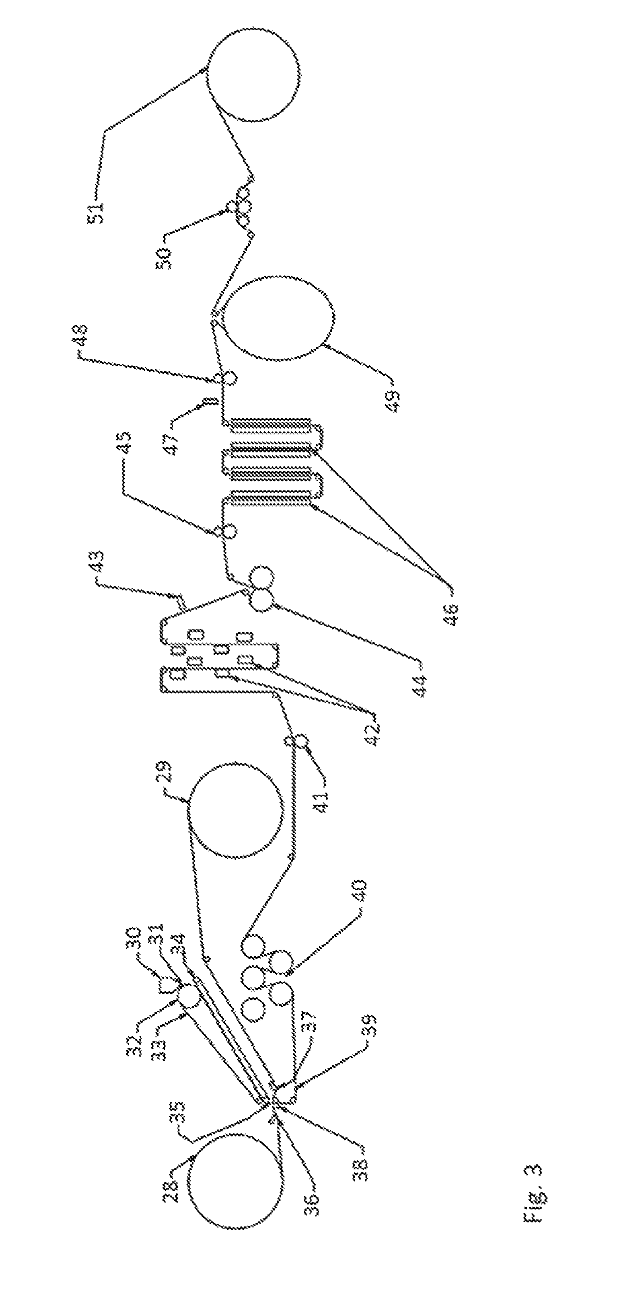
[0060]The single-step process is exemplified in FIG. 3. Two nonwoven facings 28 and 29 are unwound and a hot melt adhesive, 36 and 37, respectively, is applied in a pattern to each on a side thereof that is brought into contact with an extruded elastomeric film 31. The extruded film results from a polymeric composition, for example a styrenic block co-polymer, held in a die 30 and extruded therefrom onto a conveyer belt 33 and chilled by a chilled roll 32. The chilled extruded film 31 is then transported between conveyer belts 33 and 34 to a nip unit 38 where the two nonwoven facings having hot melt adhesive patterned thereon are applied, adhesive side facing the extruded film, one to either side of the chilled extruded film so as to produce a laminated web 39. The laminated web 39 is transported through a plurality of chilled rolls 40 and fed via a drive nip station 41 through a web heating station 42 to activation unit 44. An exemplary activation unit is more fully described in FI...


PUM

PropertyMeasurementUnit
angleaaaaaaaaaa
angleaaaaaaaaaa
widthaaaaaaaaaa

Abstract

A process for making an elastomeric laminated product including the steps of laminating an elastomeric film between a first spunbond nonwoven layer and a second spunbond nonwoven layer so as to form a laminated web, transporting the laminated web through intermeshing rollers so as to strain portions of the laminated web to form activated regions in the laminated web, and transporting the activated laminated web to a first portion of a rotating wheel, the first portion of the wheel having a cross direction width that is smaller than a cross direction width at a second portion of the wheel, so that the laminated web follows rotation of the wheel and is stretched in the cross direction at the second portion of the wheel before separating from the wheel at the first portion in a relaxed state.

Description

RELATED APPLICATION[0001]This application is a non-provisional based on and claiming priority to U.S. Provisional Patent Application No. 62 / 150,505, filed Apr. 21, 2015, entitled MANUFACTURING PROCESS FOR ELASTOMERIC LAMINATE, the contents of which are incorporated herein by reference in their entirety.BACKGROUND OF THE INVENTION[0002]Manufacture of elastomeric laminates which do not subsequently delaminate is a challenging process. Specific control over product quality attributes is critical. The predominant manufacturing method for making elastomeric laminates is a two-step process where in the first step preparation of a laminated roll is performed, and then in a second step the laminated roll is converted into an activated, cross direction elastic laminate web, wound onto a roll.[0003]Several parameters and tools are used to characterize the properties of the resultant elastomeric laminate, including percentage degradation under a given gram-force value, displacement resulting f...

Claims


Application Information

Patent Timeline
Patent Type & Authority Patents(United States)
IPC IPC(8): B32B37/00B29C53/26B29C55/02B29C55/08B32B25/14B32B5/08B32B7/12B32B7/14B32B25/10B32B5/00B32B5/02B32B37/20B29C53/84B32B38/00B32B37/06B32B37/08B32B37/12B29L31/48
CPCB32B25/14B32B5/08B32B37/0053B32B5/00B32B5/022B29C55/023B29C55/08B32B25/10B29C53/265B32B7/14B32B7/12B32B2262/12B32B2307/718B29C53/84B29L2031/4878B32B38/0012B32B37/08B32B2037/1215B32B2555/02B32B37/06B32B2038/0028B32B2262/0253B32B2250/03B32B2270/00B32B37/1292B32B2305/20B32B2250/40B32B37/20
Inventor DOYLE, JEREMY A.KELLEY, JR., RICHARD EUGENECAPPELLINI, PIERLUIGI
Owner FIRST QUALITY BABY PROD
Learn More