Energy storage apparatus and control method of energy storage devices

a technology of energy storage devices and energy storage devices, which is applied in the direction of secondary cell servicing/maintenance, cell components, batteries, etc., to achieve the effects of preventing the occurrence of a malfunction in the energy storage device, and increasing the charge current valu

Active Publication Date: 2022-05-05
GS YUASA INT LTD
View PDF8 Cites 2 Cited by
  • Summary
  • Abstract
  • Description
  • Claims
  • Application Information

AI Technical Summary

Benefits of technology

[0008]When a plurality of energy storage devices are connected in series, the total sum of voltages of the respective energy storage devices and a charge voltage are identical. A control unit discharges only an energy storage device having a highest voltage and continues charging of the other plurality of energy storage devices, thereby relatively increasing charge current values of the other plurality of energy storage devices. Then, voltages of the other plurality of energy storage devices become easy to increase, and thus a voltage of the energy storage device having the highest voltage becomes easy to decrease. In this manner, the voltage of the energy storage device having the highest voltage can be quickly reduced, and charging of the energy storage device can be continued.
[0009]When a state that discharging is not in time and the voltage of the energy storage device having the highest voltage exceeds a first voltage threshold continues for a first duration, the control unit stops charging. Alternatively, when a state that the voltage of the energy storage device having the highest voltage exceeds a second voltage threshold elapses a second duration, the control unit stops charging the energy storage device, and thus occurrence of a malfunction in the energy storage devices can be prevented.
[0010]Thus, charging can be continued so that a malfunction does not occur in an energy storage device having a highest voltage.

Problems solved by technology

The plurality of energy storage devices connected in series generate variations in charge capacity among the energy storage devices due to an imbalance in electrical characteristics.

Method used


Image

  • Energy storage apparatus and control method of energy storage devices
  • Energy storage apparatus and control method of energy storage devices
  • Energy storage apparatus and control method of energy storage devices

Examples


first embodiment

[0038]A first embodiment will be described with reference to FIGS. 1 to 9.

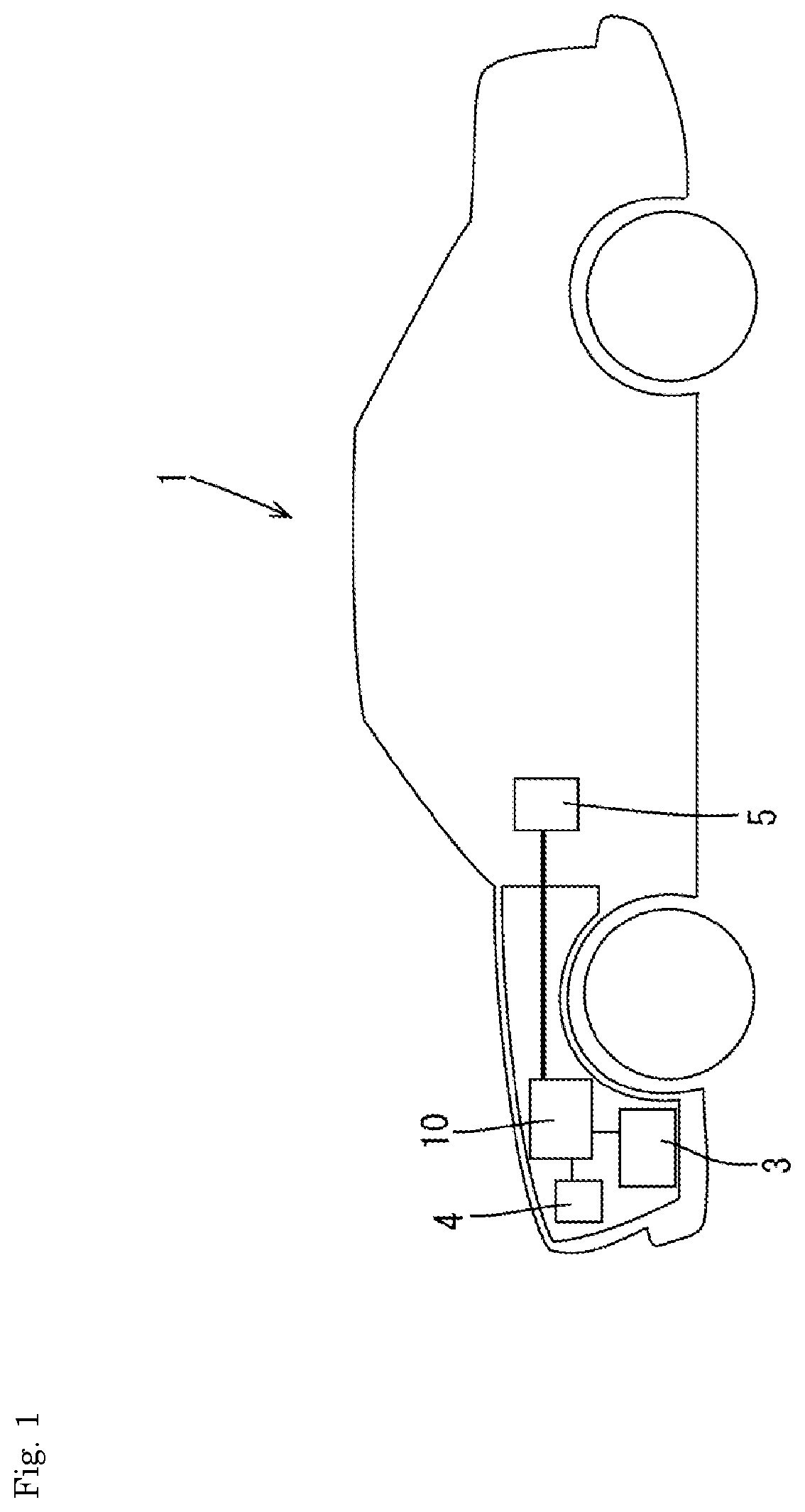
[0039]As illustrated in FIG. 1, an energy storage apparatus 10 for starting an engine installed in a vehicle 1 such as an automobile will be illustrated. The energy storage apparatus 10 is connected to a vehicle load 3 such as an engine starter motor and electrical components mounted on the vehicle 1, a vehicle generator 4 such as an alternator, a vehicle Electronic Control Unit (ECU) 5, and the like.

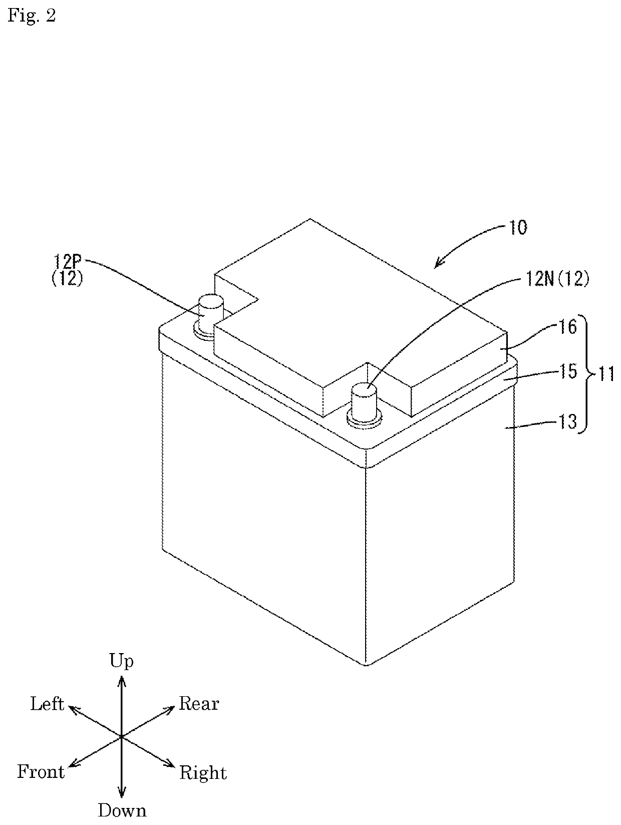
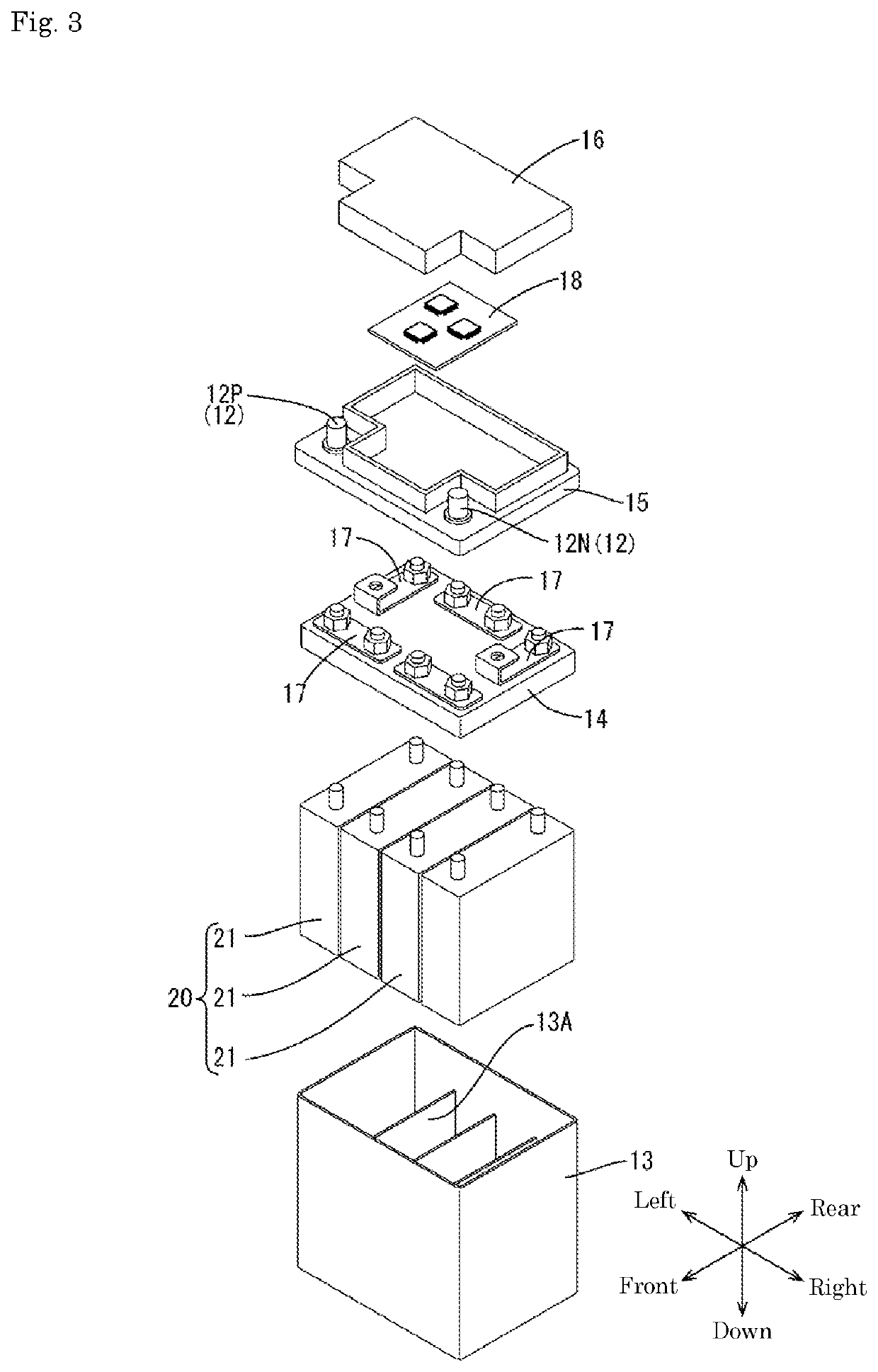
[0040]The energy storage apparatus 10 has a block-shaped battery case 11 as illustrated in FIG. 2. As illustrated in FIG. 3, the battery case 11 houses an assembled battery 20, a control board 18, and the like. The assembled battery 20 includes a plurality (four in this embodiment) of energy storage devices 21 connected in series.

[0041]In the following description, when referring to FIGS. 2 and 3, a vertical direction is based on a vertical direction of the battery case 11 when the battery case 11 is placed horizo...

second embodiment

[0092]A second embodiment will be described with reference to FIG. 10.

[0093]A charge control process of the second embodiment is changed in part from the charge control process of the first embodiment. In the following description, since configurations, operations, and effects common to the first embodiment are redundant, descriptions thereof are omitted. Further, the same reference signs are used for the same configurations as those of the first embodiment.

[0094]In the charge control process of the second embodiment, as illustrated in FIG. 10, the CPU 33 determines whether the cell voltages of the energy storage devices 21 exceed the first voltage threshold (4.0 [V]) (S11). In the process of S11, when the cell voltage of the highest-voltage energy storage device 21U has exceeded the first voltage threshold (YES in S11), the CPU 33 calculates a voltage difference between the cell voltage of the highest-voltage energy storage device 21U and the cell voltage of the lowest-voltage ener...


PUM

PropertyMeasurementUnit
voltageaaaaaaaaaa
voltageaaaaaaaaaa
cell voltageaaaaaaaaaa

Abstract

An energy storage apparatus includes: a plurality of energy storage devices connected in series; a voltage detection unit that detects voltages of the plurality of energy storage devices; a discharge circuit that discharges the energy storage devices; and a control unit. The energy storage devices include lithium ion cells. The plurality of energy storage devices is chargeable by an external charger for a lead-acid battery, wherein a charge voltage per cell of the external charger for the lead-acid battery is higher than a maximum voltage of the energy storage device, and wherein the control unit discharges only an energy storage device having a highest voltage out of the plurality of energy storage devices when the plurality of energy storage devices is charged by a charger.

Description

[0001]The present application is a Divisional Application of U.S. patent application Ser. No. 16 / 498,941, filed on Sep. 27, 2019, which is based on International Patent Application No. PCT / JP2018 / 014544, filed on Apr. 5, 2018, and Japanese Patent Application No. 2017-075143, filed on Apr. 5, 2017, the contents of which is incorporated herein by reference in its entirety.TECHNICAL FIELD[0002]The technology disclosed in the present description relates to an energy storage apparatus and a control method of energy storage devices.BACKGROUND ART[0003]Conventionally, there has been an energy storage apparatus in which a plurality of energy storage devices are connected in series to obtain a predetermined voltage. The plurality of energy storage devices connected in series generate variations in charge capacity among the energy storage devices due to an imbalance in electrical characteristics. A battery charger described in Patent Document 1 below has a discharge circuit (bypass circuit) i...

Claims


Application Information

Patent Timeline
Patent Type & Authority Applications(United States)
IPC IPC(8): H02J7/00H01M10/44H01M10/0525H01M10/48H01M10/42H02J7/16H01M50/209
CPCH02J7/0047H01M10/441H01M10/0525H01M2010/4271H01M10/425H02J7/16H02J7/0014H01M10/482H01M10/44H01M10/48H02J7/02H02J7/0016H02J2310/40H01M2220/20Y02E60/10H01M50/209
Inventor FUKUSHIMA, ATSUSHI
Owner GS YUASA INT LTD
Why Eureka
Try Eureka