Dental Device

Pending Publication Date: 2022-05-12
MOORE PAUL +1
View PDF0 Cites 0 Cited by
  • Summary
  • Abstract
  • Description
  • Claims
  • Application Information

AI Technical Summary

Benefits of technology

[0039]The sheet may comprise one or more breathing holes located on the sheet. The breathing holes allow the patient to breathe through their mouth during the procedure and further allows a dentist to use a saliva ejector to remove saliva from the patient's mouth during a dental procedure. The breathing holes may be offset laterally from a central horizontal axis of the sheet. This is beneficial as it a

Problems solved by technology

Furthermore, the dental device may control the position of the soft tissue within a patient's mouth suc

Method used


Image

  • Dental Device
  • Dental Device
  • Dental Device

Examples


Embodiment Construction

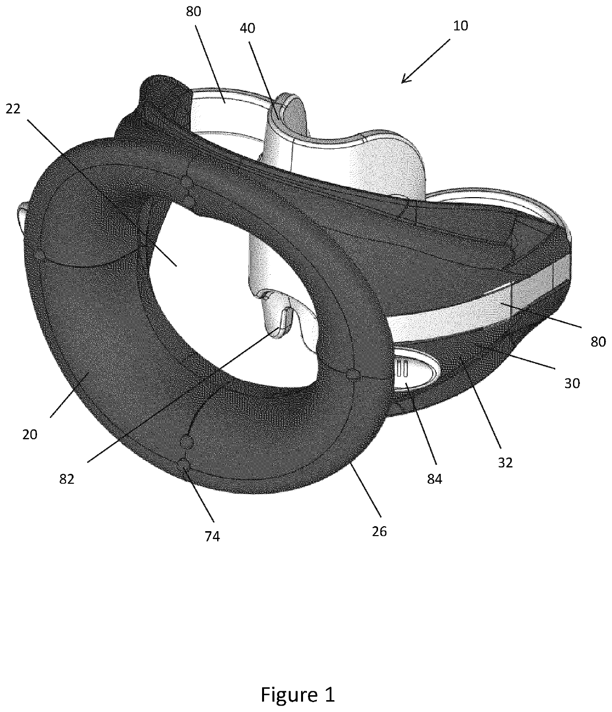
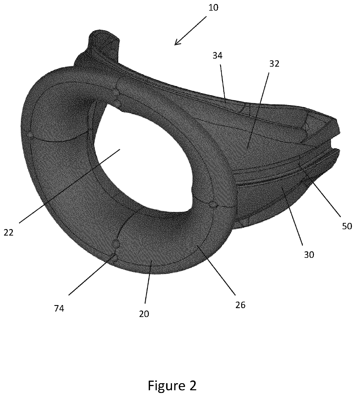
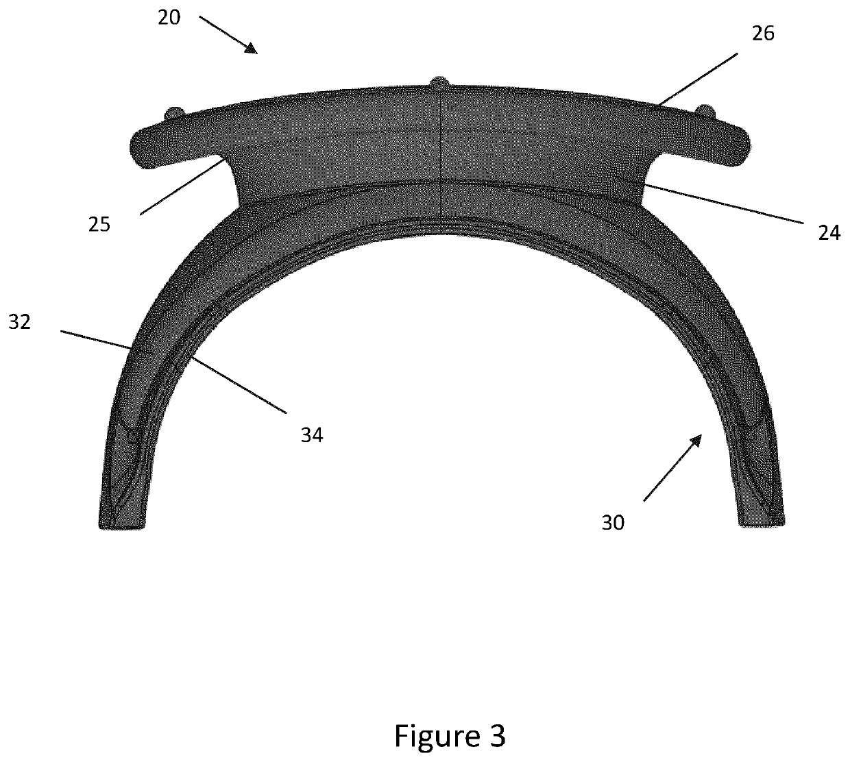
[0073]In general terms, embodiments of the invention relate to a dental retractor for controlling the position of soft tissue, such as the tongue, cheeks and lips, within the mouth of a dental patient during a dental procedure. The retractor comprises a circumferential lip retractor for promoting movement of a patient's lips away from their teeth such that the patient's lips do not obscure their teeth from view. The retractor further comprises a cheek retractor for moving the inner surface of a patient's cheek away from their lower and upper dental arches. The cheek retractor may comprise a pair of arcuate arms extending distally from the lip retractor along an arcuate path representative of the dental arch.

[0074]A tongue retractor may be removably coupled to the cheek retractor to control movement of a patient's tongue. The tongue retractor beneficially prevents the patient moving their tongue during a dental procedure as this may inhibit the dentist during the procedure. Furthermo...


PUM


Abstract

Aspects of the present invention relate to a dental retractor for controlling the position of soft tissue within a mouth, the dental retractor comprising: a lip retractor for controlling the position of a lip; and a cheek retractor comprising a pair of arms for controlling the position of a cheek; and wherein the dental retractor comprises a tongue retractor removably coupled to the dental retractor for controlling the position of a tongue.

Description

TECHNICAL FIELD[0001]The present disclosure relates to a dental device, and in particular but not exclusively, to a dental retractor for controlling the position of soft tissue within a patient's mouth. Aspects of the invention relate to a dental retractor, to a dental contraster, to a tongue retractor and to a sheet.BACKGROUND[0002]During a dental procedure dentists require unobstructed access to a patient's mouth. Typically this is achieved by the patient holding their mouth open for a sustained period of time during the procedure in order to provide access to their teeth. During a dental procedure the dentist may be assisted by a dental assistant who can hold, for example, the patient's cheeks or lips out of the way of the dentist to avoid any unwanted obstructions during the dental procedure.[0003]It is known to use various tools to aid the dentist or their assistant during a procedure. For example, a dentist may use a retractor device to control the position of soft tissue, suc...

Claims


Application Information

Patent Timeline
IPC IPC(8): A61C5/90A61C5/82
CPCA61C5/90A61C5/82A61B1/24A61C17/10A61B13/00A61C17/096
Inventor MOORE, PAULHENDY, HAZEL
Owner MOORE PAUL
Why Eureka
Try Eureka