Locking Wheel Chock

a technology of locking wheel and chock, which is applied in the field of locking wheel chock, can solve the problems of occupying a lot of floor space, requiring significant time and effort to install and de-install, and systems are not typically easily reconfigurable, so as to achieve quick removal or re-installation, easy movement into storage, and quick transition

Pending Publication Date: 2022-05-19
SULLIVAN RYKER ALAN +1
View PDF0 Cites 0 Cited by
  • Summary
  • Abstract
  • Description
  • Claims
  • Application Information

AI Technical Summary

Benefits of technology

[0012]In another aspect of the invention is one of the various mounting assemblies called the detachable mount assembly. The detachable mount assembly is designed in two parts. One section, part A, is secured to one of the above mentioned mounting assemblies and the other section, part B, is secured to the wheel chock assembly. With the removal or installation of one fastener the wheel chock assembly and detachable mount assembly part B are quickly removed or re-installed. The detachable two part mount assembly with the wheel chock assembly mounted to it and when installed to the one of the other mounting assemblies, (ie.. rail mount, bed mount, floor mount) listed above allows the wheel chock assembly to be quickly released from a mounting assembly so that the wheel chock assembly / part B can be easily moved into storage or even to one of the other mount assemblies that have a part A already attached so that the user can quickly transition between vehicles and trailers.

Problems solved by technology

Typically, these systems require significant time and effort to install and de-install.
These systems are not typically easily reconfigurable from one type of vehicle or trailer to another and take up a lot of floor space when not in use and limits what a person can haul.
Additionally, these various wheel chocks only clamps a wheel which limits their potential for securing the motorcycle and / or bicycle from theft.

Method used


Image

  • Locking Wheel Chock
  • Locking Wheel Chock
  • Locking Wheel Chock

Examples


Embodiment Construction

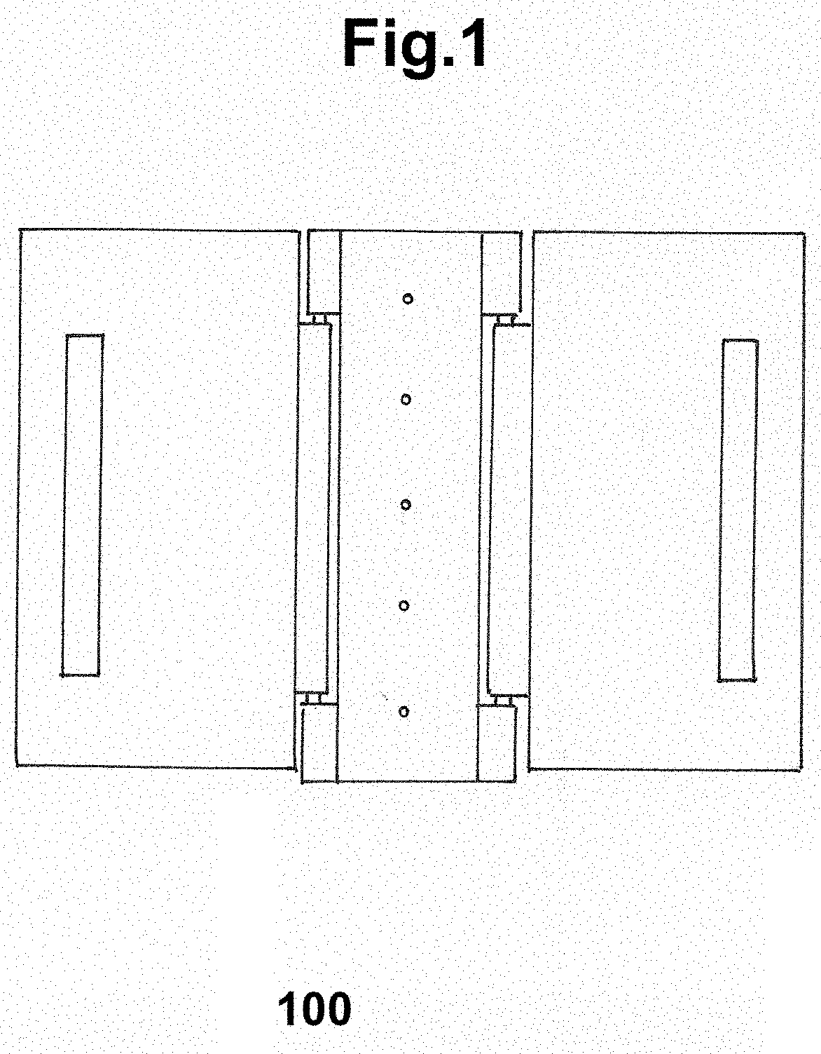
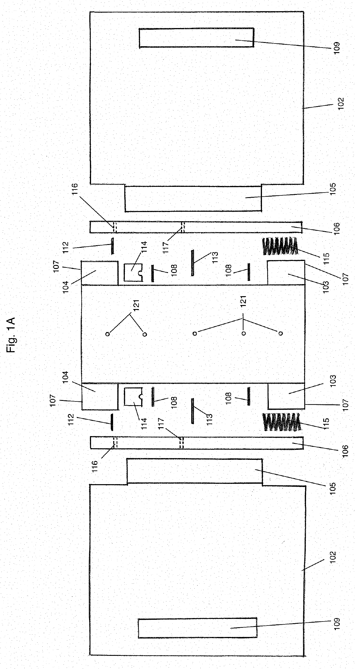
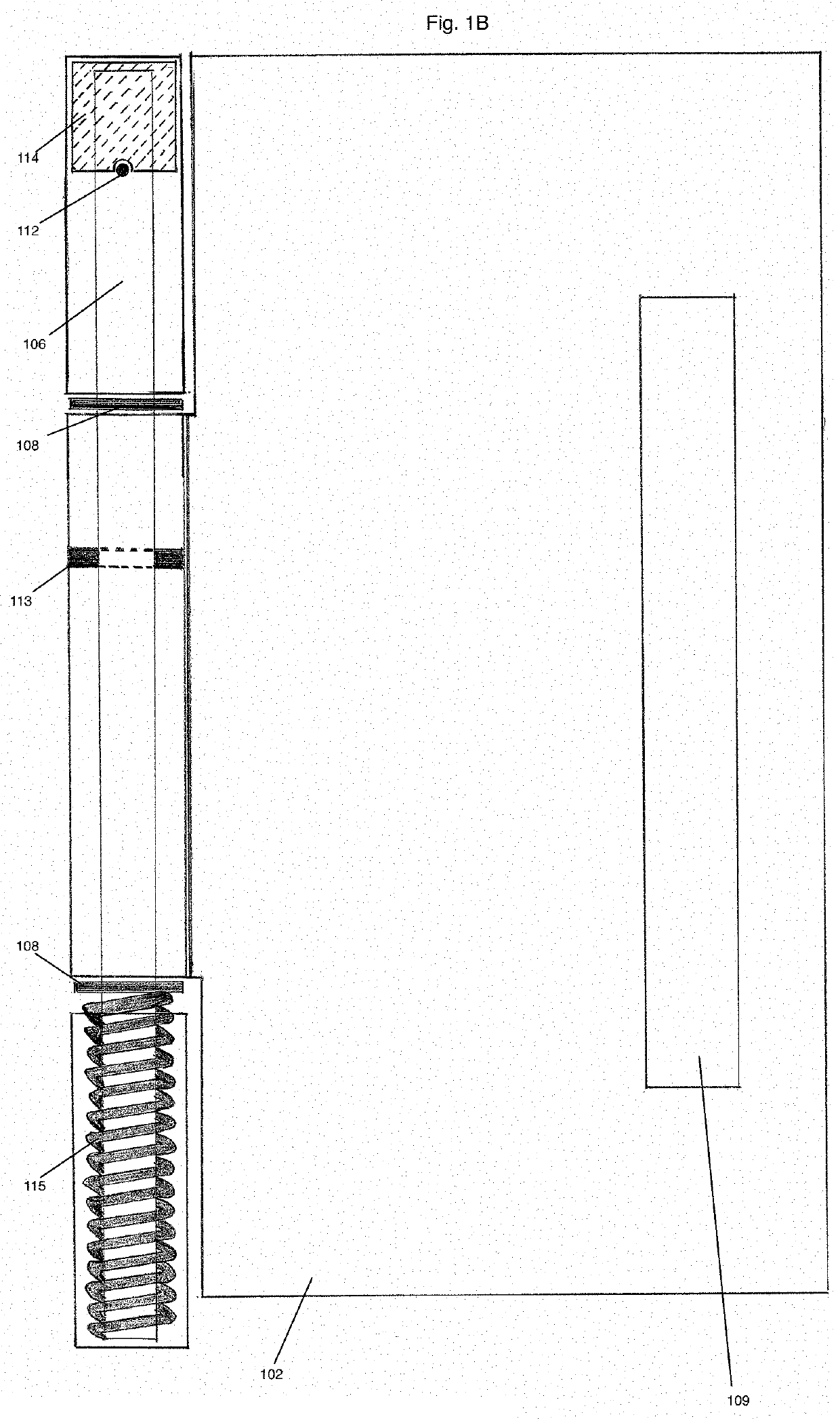
[0013]Referring now to FIG. 1, throughout this description and the accompanying drawings reference is made to principles of the invention through the use of exemplary embodiments. It should be understood that the application is not limited to the details or specific methodologies set fourth herein. It should also be understood that the terminology used herein is for the purpose of description only and should not be regarded as limiting. In the following description, for purpose of explanation, numerous specific details are set fourth in order to provide a thorough understanding of the present systems and methods. It will be apparent, however, to one skilled in the art that the present apparatus, systems and methods may be practiced without these specific details. Reference in the specification to “an example” or similar language means that a particular feature, structure, or characteristic described in connection with the example is included in at least that one example, but not nec...


PUM


Abstract

A wheel chock assembly to secure a wheel of a motorcycle and/or bicycle by encasing the wheel and secured by a lockable lock pin. The wheel chock assembly can be used with one of the various mounting assemblies and with the frame securement collar assembly. The wheel chock assembly when mounted on one of the various mounting assemblies can be used to secure a motorcycle and/or bicycle on the bed of a truck or on the bed wall of a truck, trailer floor, trailer wall or trailer railing and even in a garage on the floor or wall. The securement collar assembly is used either around the steering column and frame attaching to the wheel chock assembly's lock pin for securement or between the rear tire and the frame attaching to the wheel chock assembly's lock pin for securement.

Description

FIELD OF THE INVENTION[0001]Some embodiments disclosed in this application relate to devices used to secure at least one motorcycle or other similar vehicle to the bed of a truck or floor / railing of a transport vehicle including, but not limited to, recreational vehicles (RV's), toy haulers, and trailers.BACKGROUND OF THE INVENTION[0002]Transportation of motorcycles and bicycles in pickups, trucks and trailers are a common occurrence. Various wheel chocks systems have been developed to allow for transportation of motorcycles and / or bicycles in pickups, trucks and trailers. Some of the various wheel chocks offer some type of securement from theft while others do not. Many of these traditional wheel chock systems are physically attached to a pickup, truck and trailer. Typically, these systems require significant time and effort to install and de-install. These systems are not typically easily reconfigurable from one type of vehicle or trailer to another and take up a lot of floor spac...

Claims


Application Information

Patent Timeline
Patent Type & Authority Applications(United States)
IPC IPC(8): B60P3/077B62H3/04B60P7/08B62H5/14
CPCB60P3/077B62H5/145B60P7/08B62H3/04B62H5/003
Inventor SULLIVAN, RYKER ALANSULLIVANE, MICHAEL THOMAS
Owner SULLIVAN RYKER ALAN
Why Eureka
Try Eureka