Free streamline airfoil

Pending Publication Date: 2022-05-26
BROWN UNIVERSITY
View PDF4 Cites 0 Cited by
  • Summary
  • Abstract
  • Description
  • Claims
  • Application Information

AI Technical Summary

Benefits of technology

[0008]In general, in one aspect, the invention features a free-streamline airfoil including a lower surface which is flat or contoured, and an upper surface that is curved or made of discrete flat elements approximating a curved surface, the upper su

Problems solved by technology

When a chord based Reynolds number of an airfoil decreases, the airfoil power factor is greatly limited by a reduction in the maximum lift and the occurrence of large flow separation from the airfoil that increases drag.
The poor aerodynamic power fac

Method used


Image

  • Free streamline airfoil
  • Free streamline airfoil
  • Free streamline airfoil

Examples


Example

[0031]The subject innovation is now described with reference to the drawings, wherein like reference numerals are used to refer to like elements throughout. In the following description, for purposes of explanation, numerous specific details are set forth in order to provide a thorough understanding of the present invention. It may be evident, however, that the present invention may be practiced without these specific details. In other instances, well-known structures and devices are shown in block diagram form in order to facilitate describing the present invention.

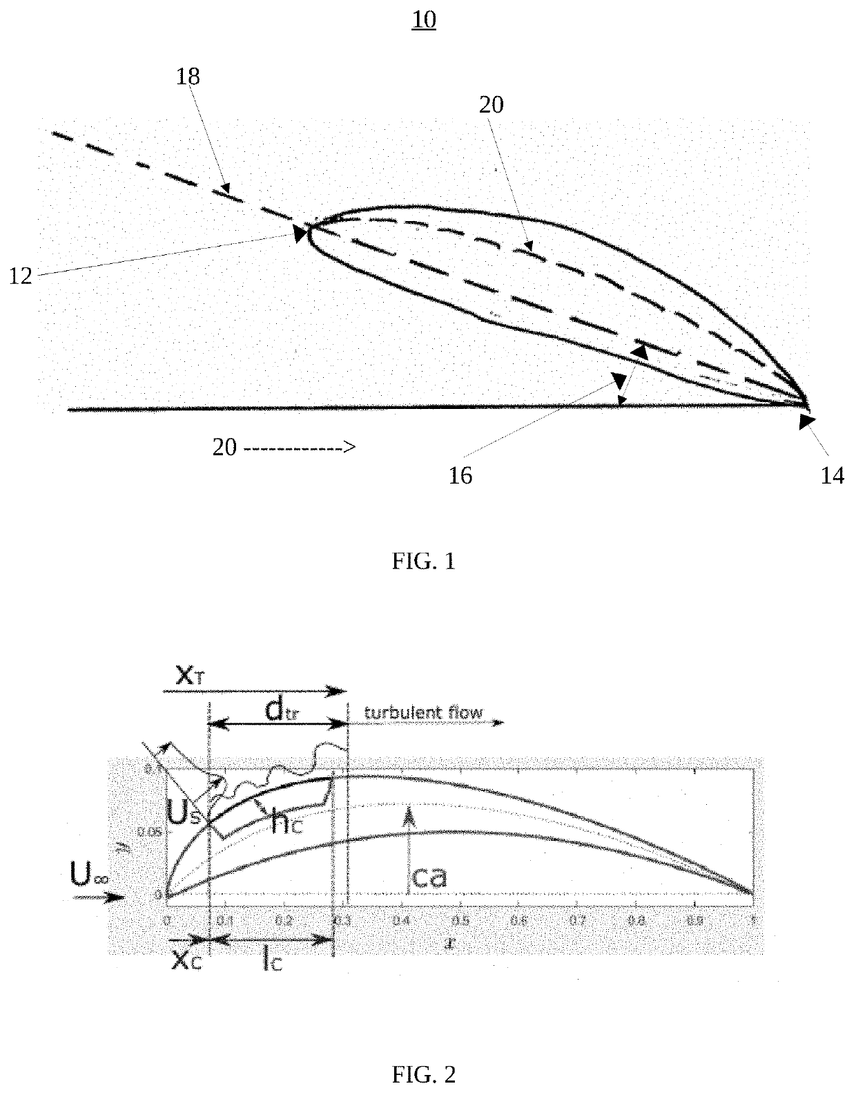
[0032]In general, lift and weight are two of the four forces acting on a drone or airplane, the other two being drag and thrust. A drone or airplane generates lift using its wings. A cross-sectional shape of a wing is typically referred as an airfoil. As shown in FIG. 1, an exemplary airfoil 10 includes a leading edge 12, a trailing edge 14, an angle of attack 16, a chord 18, a camber line 20 and an air flow 22. The chor...


PUM


Abstract

A free-streamline airfoil includes a lower surface which is flat or contoured, and an upper surface that is curved or made of discrete flat elements approximating a curved surface, the upper surface presenting a cavity, a cavity width in an airfoil chordwise direction shorter than the airfoil chord, a position and depth of the cavity triggering a turbulent flow over the airfoil's suction side while preserving the airfoil physical integrity.

Description

CROSS REFERENCE TO RELATED APPLICATIONS[0001]This application claims benefit from U.S. Provisional Patent Application Ser. No. 63 / 118,266, filed Nov. 25, 2020, which is incorporated by reference in its entirety.STATEMENT REGARDING GOVERNMENT INTEREST[0002]This invention was made with government support under grant number CMMI-1426338 awarded by the National Science Foundation. The government has certain rights in the invention.BACKGROUND OF THE INVENTION[0003]The present invention relates generally to aerodynamics systems and apparatus for the production of lift or control forces for aircraft or missiles, and more particularly, to a free streamline airfoil.[0004]In aerodynamics, the Reynolds number is a measure of the ratio of the inertial force of a gas to the viscous force, and is a dimensionless number. When the Reynolds number is smaller, the influence of the viscous force on the flow field is larger than the inertia force, the disturbance of the flow velocity in the flow field ...

Claims


Application Information

Patent Timeline
IPC IPC(8): B64C3/14B64C23/06
CPCB64C3/14B64C2003/149B64C23/06B64U30/10
Inventor DI LUCA, MATTEOBREUER, KENNETH
Owner BROWN UNIVERSITY
Why Eureka
Try Eureka