Coating thickness measurement instrument

Pending Publication Date: 2022-05-26
ELCOMETER
View PDF4 Cites 0 Cited by
  • Summary
  • Abstract
  • Description
  • Claims
  • Application Information

AI Technical Summary

Benefits of technology

[0010]The drive current may be scaled according to a first scaling factor. The detected output may be scaled according to a second scaling factor. The processor may be configured to scale the drive current and detector output according to a first scaling factor and a second scaling factor respectively. The method may include the step of storing the first and second scaling factors as a pair. The processor may be configured to store the first and second scaling factors as a pair. As such, the scaling is controlled by the value of two scaling factors that allows for convenient and repeatable measurements.
[0011]The method may comprise the step of changing the scaling applied to the drive current and/or detected output. The processor may be configured to change the scaling applied to the drive current and/or detector output. The scaling may be changed in a step-wise, or discontinuous, manner. The

Problems solved by technology

However, use of such a feedback loop can lead to slow response times for the inst

Method used


Image

  • Coating thickness measurement instrument
  • Coating thickness measurement instrument

Examples


Embodiment Construction

[0032]In order that the invention may be more clearly understood one or more embodiments thereof will now be described, by way of example only, with reference to the accompanying drawings, of which:

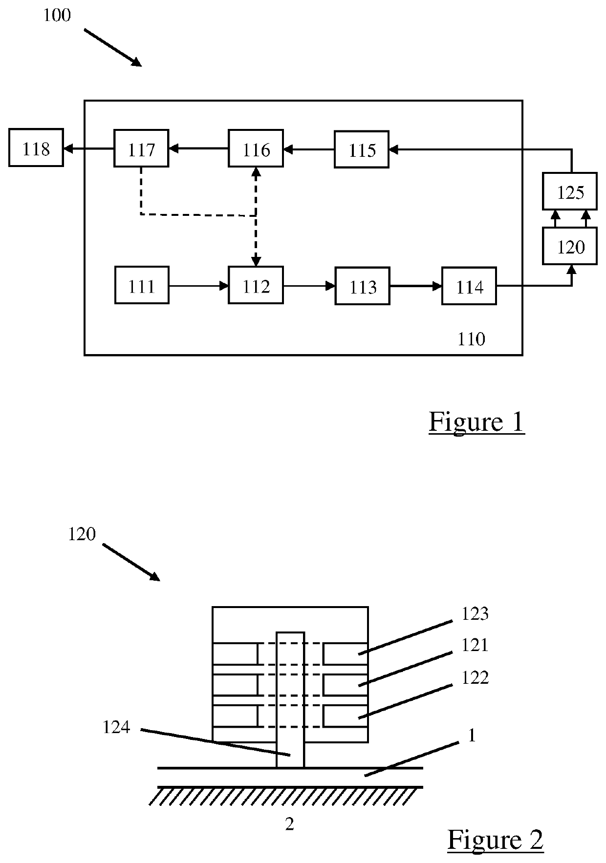
[0033]FIG. 1 is a schematic diagram of a coating thickness measurement instrument;

[0034]FIG. 2 is a schematic diagram of a probe comprised in the instrument of FIG. 1 in use;

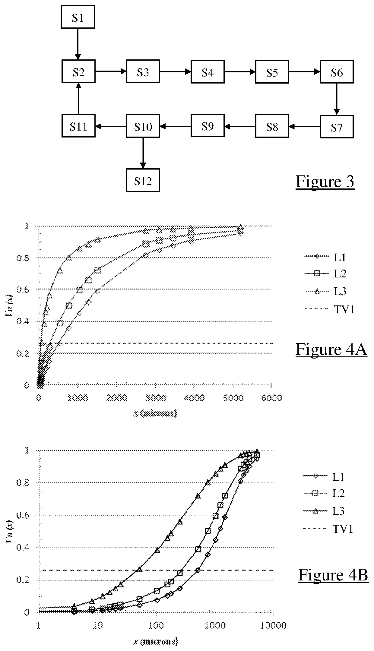
[0035]FIG. 3 is a flow diagram for the process the instrument of FIG. 1 follows to take a measurement;

[0036]FIG. 4A is a graph comparing the normalised output Vn(x) against coating thickness x for three coating thickness measurement instruments, including the instrument of FIG. 1; and

[0037]FIG. 4B is the graph of FIG. 4A with a logarithmic scale applied to the coating thickness.

[0038]Referring to FIGS. 1 and 2, a coating thickness measurement instrument 100 comprises a microprocessor controller 110, a coating thickness probe 120, an amplifier 125, and a user interface 118 connected electronically. The controller 110, ...


PUM


Abstract

A coating thickness measuring instrument comprising: a magnetic induction probe comprising at least one drive coil and at least one pick-up coil; a driver for driving an alternating current in the or each drive coil; and a detector for detecting the output of the or each pick-up coil; and a processor configured to: apply a transfer function to the detector output to produce an output which corresponds to a measured coating thickness; and, scale both the drive current and detector output simultaneously in response to the output. The scaling may be changed in a step-wise manner. The scaling applied to the drive current may be inversely proportional to the scaling applied to the detector output. The scaling may be defined by a first and second scaling factor, stored as a pair. The instrument may store two or more pairs of scaling factors and select a pair in response to the measured coating thickness.

Description

TECHNICAL FIELD OF THE INVENTION[0001]The present invention relates to coating thickness measurement instruments, in particular to inductive coating thickness instruments.BACKGROUND TO THE INVENTION[0002]An existing coating thickness measurement instrument is disclosed in GB2367135A. The instrument is controlled according to two modes of operation. In the first mode, the instrument operates over a short range of coating thicknesses but with high resolution. In the second mode, the instrument can measure a greater range of coating thicknesses than the first mode, but with a reduction in resolution.[0003]The instrument disclosed in GB2367135A switches between each mode by activating a feedback loop that automatically varies the electronic gain of the instrument in the second mode. However, use of such a feedback loop can lead to slow response times for the instrument and time-invariant measurements due to instabilities in the feedback loop.[0004]It is an object of embodiments of the p...

Claims


Application Information

Patent Timeline
IPC IPC(8): G01B7/06
CPCG01B7/105G01B7/06
Inventor MAY, PHILIP ANTHONYCOULTON, SIMON TREVENADODD, ALAN JAMESJIMENEZ-LOPEZ, MARIA ISABEL
Owner ELCOMETER
Why Eureka
Try Eureka