
Steam turbine blade, steam turbine, and method for operating same

Pending Publication Date: 2022-06-02
MITSUBISHI HEAVY IND LTD
View PDF0 Cites 0 Cited by
  • Summary
  • Abstract
  • Description
  • Claims
  • Application Information

AI Technical Summary

Benefits of technology

The present invention provides a steam turbine blade, a steam turbine, and a method for operating the same that can further reduce the decrease in efficiency due to moisture.

Problems solved by technology

When a liquid droplet collides with a member on the downstream side (for example, a rotating blade), damage called erosion and a braking effect on the rotation of the rotating blade occur, and there is a possibility that a stable operation of the steam turbine may be hindered and that the efficiency of the steam turbine may decrease.

Method used


Image

  • Steam turbine blade, steam turbine, and method for operating same
  • Steam turbine blade, steam turbine, and method for operating same
  • Steam turbine blade, steam turbine, and method for operating same

Examples


Embodiment Construction

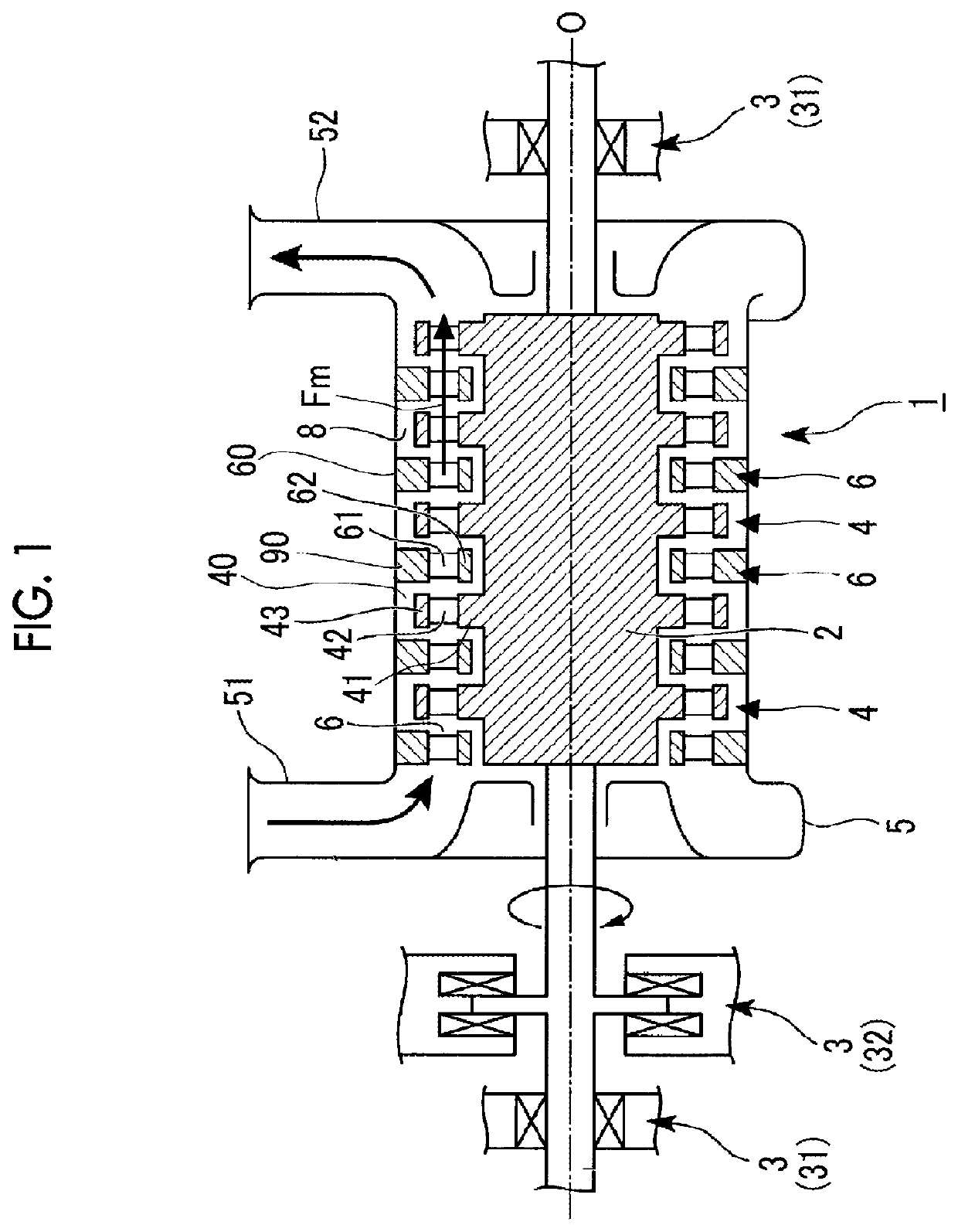
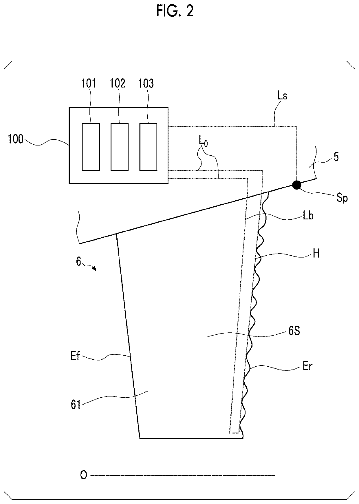
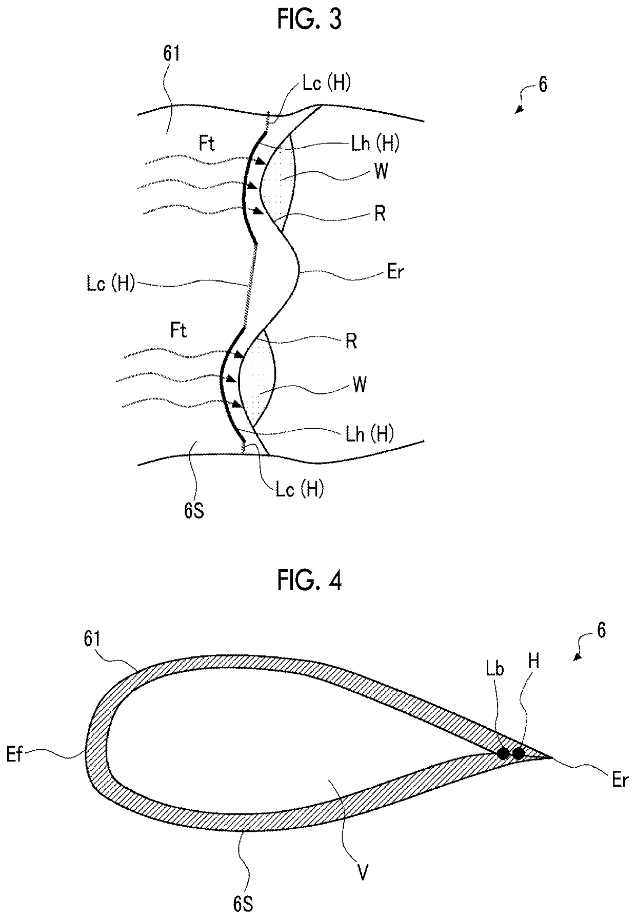
[0036]Next, an embodiment of the present invention will be described with reference to FIGS. 1 to 4. A steam turbine 1 according to the present embodiment includes a rotating shaft 2, a bearing device 3, a plurality of rotating blade stages 4, a casing 5, and a plurality of stator vane stages 6. The rotating shaft 2 has a columnar shape extending along an axis O, and can rotate around the axis O. The bearing device 3 supports the shaft end of the rotating shaft 2. The bearing device 3 has a pair of journal bearings 31 and only one thrust bearing 32. The pair of journal bearings 31 are respectively provided at both end portions of the rotating shaft 2 in an axis O direction. Each of the journal bearings 31 supports a radial load with respect to the axis O. The thrust bearing 32 is provided on only one side in the axis O direction. The thrust bearing 32 supports a load in the axis O direction. The plurality of rotating blade stages 4 arranged at intervals in the axis O direction are p...


PUM


Abstract

This steam turbine blade is provided with: a blade body (61) extending in a radial direction and having an airfoil profile in a cross section perpendicular to the radial direction; and a heater (H) including a heating wire disposed so as to extend along a trailing edge (Er) of the airfoil profile in the blade body (61). This configuration makes it possible to further mitigate an efficiency drop due to moisture attached to the surface of the steam turbine blade (60).

Description

TECHNICAL FIELD[0001]The present invention relates to a steam turbine blade, a steam turbine, and a method for operating the same.[0002]Priority is claimed on Japanese Patent Application No. 2019-101997 filed on May 31, 2019, the content of which is incorporated herein by reference.BACKGROUND ART[0003]There are cases where water droplets adhere to the surface of a stator vane of a steam turbine as steam flows. Such water droplets form a water film on the blade surface, and the water film is released into the steam from the trailing edge of the stator vane and is made finer and becomes enlarged liquid droplets in a high-speed steam environment. The enlarged liquid droplets flow downstream along with the flow of the steam. When a liquid droplet collides with a member on the downstream side (for example, a rotating blade), damage called erosion and a braking effect on the rotation of the rotating blade occur, and there is a possibility that a stable operation of the steam turbine may b...

Claims


Application Information

Patent Timeline
IPC IPC(8): F01D5/18F01D21/12F01D21/10
CPCF01D5/18F01D21/12F01D21/10F05D2260/608F05D2270/303F05D2270/301F05D2220/31F01D25/32F05D2240/125F01D19/02F01D25/10F01D9/02
Inventor SENOO, SHIGEKI
Owner MITSUBISHI HEAVY IND LTD
Learn More