
Temperature-control system for mr apparatuses with a permanent magnet arrangement

Pending Publication Date: 2022-06-02
BRUKER SWITZERLAND AG
View PDF4 Cites 0 Cited by
  • Summary
  • Abstract
  • Description
  • Claims
  • Application Information

AI Technical Summary

Benefits of technology

The present invention is a temperature control system for an NMR magnet system that aims to improve its performance. The system can set a variable test sample temperature, change shim currents quickly without causing the magnet system to drift, achieve a large maximum amplitude of the lock range without slow drifting and modified field gradients, and control the temperature of the permanent magnet to achieve a constant or stable temperature gradient. The system also ensures increased field stability, regardless of heat input due to shim currents or in the region of the measuring chamber. Additionally, the system can control the temperature of the permanent magnet to irrespective of heat input from external influences.

Problems solved by technology

If very warm / cold test samples are introduced, this leads to detrimental B0 homogeneity variations as a result of temperature gradients emerging in the magnet system.
This leads to considerable losses in the S / N as a result of a reduced test sample volume.
This can cause major problems, for example if solutions precipitate, for example if they are supersaturated in the region of the magnet temperature.
However, precise temperature control in the mK range cannot be achieved using this appliance.
Accurate T-control in the mK range is not possible in this appliance either, since it does not comprise a closed chamber.
However, precise T-control of the magnet is not the focus.
However, it does not address controlling the temperature of the magnet.

Method used


Image

  • Temperature-control system for mr apparatuses with a permanent magnet arrangement
  • Temperature-control system for mr apparatuses with a permanent magnet arrangement
  • Temperature-control system for mr apparatuses with a permanent magnet arrangement

Examples


Embodiment Construction

and Developments of the Invention

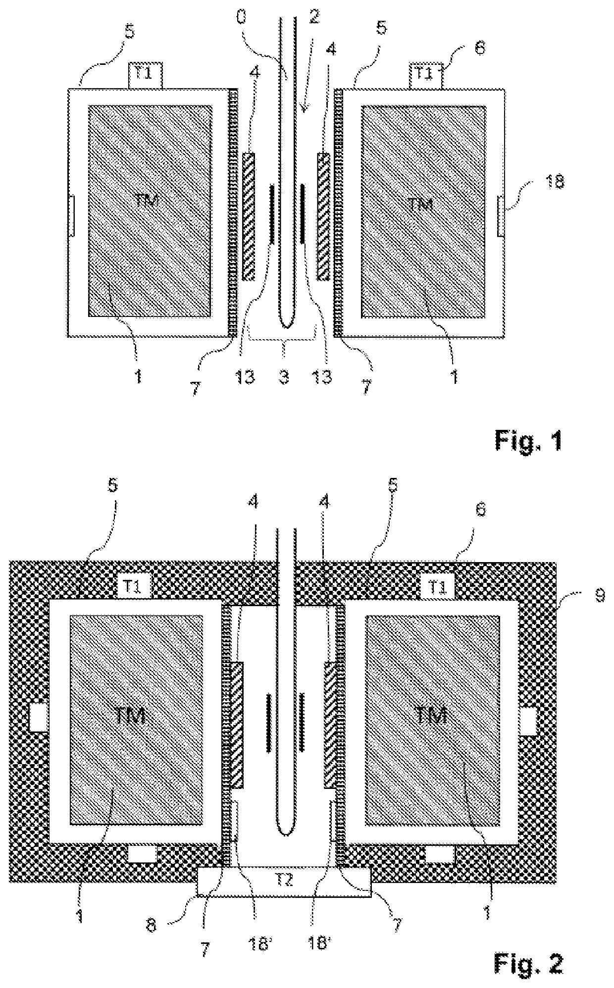
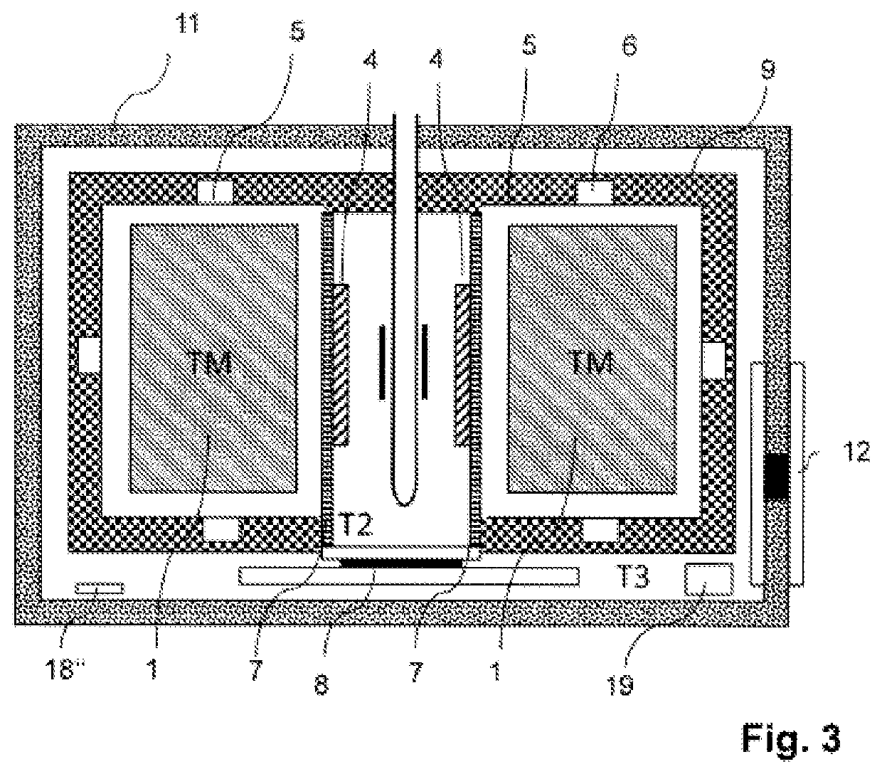
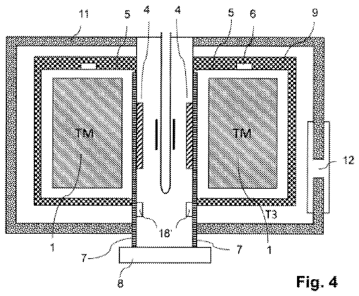
[0034]An embodiment of the temperature-control system according to the invention in which one or more arrangement controlling a temperature T2 of the heat-conducting body is arranged outside the first insulation chamber is particularly preferable. The central air gap corresponds to the hole in the magnet, in the center of which the probehead comprising the measuring chamber and the RF coil is arranged. The shim system comprising the integrated H0 coil is arranged on the radial outside, which is arranged adjacently to the permanent magnet arrangement. The generation of heat by through the currents of the shim system and the H0 coil is removed by the heat-conducting system and is given off to the environment via the heat exchanger. The temperature-control appliance controls the temperature of the heat-conducting body at the temperature T2. This ensures that the heat input towards the permanent magnet is kept constant, if T2>T1 or the heat absorption fr...


PUM


Abstract

A temperature-control system for an NMR magnet system. A permanent magnet arrangement (1) with a central air gap (2) generates a homogeneous static magnetic field inside the air gap. A probehead (3) transmits RF pulses and receives RF signals from a test sample (0). An H0 coil changes the amplitude of the static magnetic field. A shim system (4) in the air gap further homogenizes the magnetic field. A first insulation chamber (5) surrounds and thermally shields the permanent magnet arrangement and includes an arrangement (6) controlling a temperature Ti of the first insulation chamber. The shim system, the H0 coil and the NMR probehead are arranged outside the first insulation chamber in the air gap. A heat-conducting body (7) is arranged between the shim system and the H0 coil on one side and the permanent magnet arrangement on the other, thereby enhancing field stability and suppressing drift.

Description

CROSS REFERENCE TO RELATED APPLICATIONS[0001]This is a Continuation of International Application PCT / EP2020 / 072084 which has an international filing date of Aug. 6, 2020, and the disclosure of which is incorporated in its entirety into the present Continuation by reference. This Continuation also claims foreign priority under 35 U.S.C. § 119(a)-(d) to and also incorporates by reference, in its entirety, German Patent Application DE 10 2019 212 508.5 filed on Aug. 21, 2019.FIELD OF THE INVENTION[0002]The invention relates to controlling the temperature of a nuclear magnetic resonance (NMR) magnet system comprising a permanent magnet arrangement having a central air gap for generating a homogeneous static magnetic field in a measuring volume inside the central air gap, an NMR probehead for transmitting radio frequency (RF) pulses and receiving RF signals from a test sample, an NMR frequency lock comprising frequency detection in the NMR probehead and an H0 coil for changing the amplit...

Claims


Application Information

Patent Timeline
IPC IPC(8): G01R33/38G01R33/383G01R33/3875
CPCG01R33/3804G01R33/3875G01R33/383G01R33/46
Inventor FREYTAG, NICOLASHELBING, FLORIANMEISTER, ROGERZAFFALON, MICHELE
Owner BRUKER SWITZERLAND AG
Learn More