Method and system for demultiplexing and demodulating signals multiplexed in the variable orbital angular momentum

a technology of amplitude modulation and multiplexing, which is applied in the field of demultiplexing and demodulating amplitude modulated signals grouped by means of multiplexing in the orbital angular momentum variable, can solve the problems of not having reliable systems and methods allowing to detect the orbital angular momentum of electromagnetic beams, and being particularly difficult to detect and characteriz

Pending Publication Date: 2022-06-16
UNIV DELGI STUDI DI MILANO
View PDF4 Cites 1 Cited by
  • Summary
  • Abstract
  • Description
  • Claims
  • Application Information

AI Technical Summary

Benefits of technology

[0018]The present invention further relates to a system for demultiplexing and demodulating amplitude-modulated signals grouped by means of multiplexing in the orbital angular momentum variable, capable of carrying out the aforesaid method. Such a system is defined in claims 18-23.

Problems solved by technology

The “orbital angular momentum” variable, due to the features thereof mentioned above, is particularly difficult to be detected and characterized when the detector is illuminated only by a limited portion of the radiation beam, even if very distant from the singularity.
In fact, there are no reliable systems and methods allowing to detect the orbital angular momentum of an electromagnetic beam, for example, a laser, received by means of a local measure, i.e., having available only a limited portion of the beam incident on the detector, even if very distant from the singularity.
Such a need is not currently met by known technical solutions through local measures.
However, the background art in the technical field taken into consideration does not offer reliable telecommunications solutions based on orbital angular momentum multiplexing and / or modulation.

Method used


Image

  • Method and system for demultiplexing and demodulating signals multiplexed in the variable orbital angular momentum
  • Method and system for demultiplexing and demodulating signals multiplexed in the variable orbital angular momentum
  • Method and system for demultiplexing and demodulating signals multiplexed in the variable orbital angular momentum

Examples


Embodiment Construction

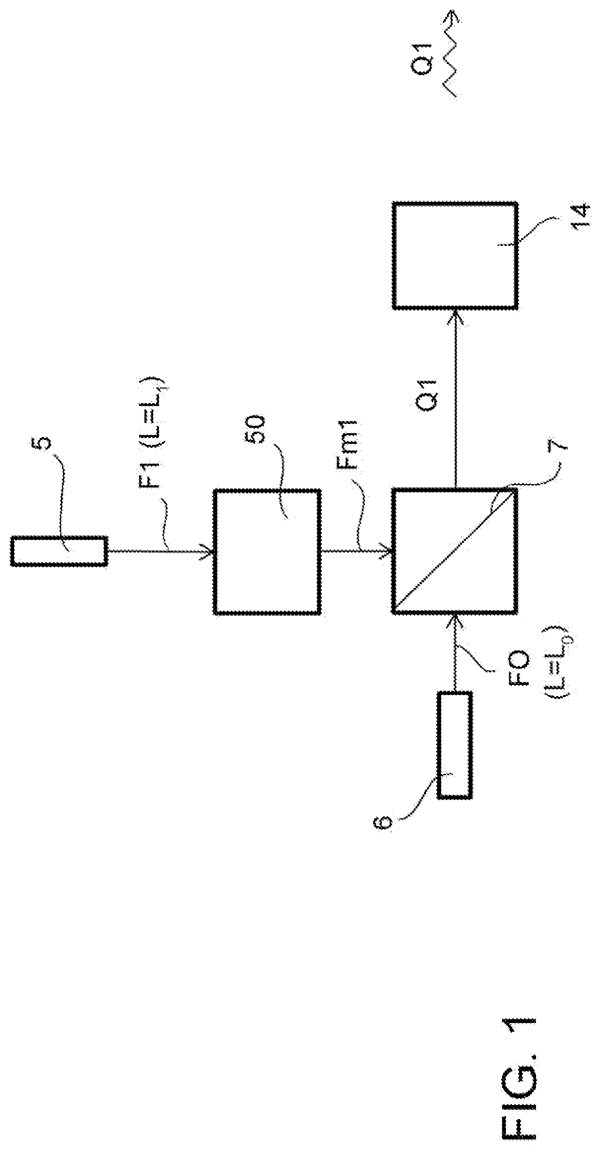
[0028]With reference to FIGS. 1 to 6, a method for transmitting and receiving an electromagnetic radiation beam is described, adapted to determine an orbital angular momentum of the received electromagnetic radiation beam.

[0029]The method, first of all, comprises the steps of generating at least one main electromagnetic radiation beam F1 characterized by a first orbital angular momentum L1, by a first spectrum in a first frequency band, and by a first beam radius of curvature, and of generating a reference electromagnetic radiation beam F0, characterized by a second orbital angular momentum L0, by a second spectrum in a second frequency band which is distinct from the aforesaid first frequency band, and by a second beam radius of curvature substantially coinciding with the aforesaid first beam radius of curvature.

[0030]It should be noted that the aforesaid characterization based on a first L1 and a second orbital angular momentum Lo may be correspondingly described also in terms of ...


PUM

PropertyMeasurementUnit
orbital angular momentumaaaaaaaaaa
frequencyaaaaaaaaaa
frequency bandaaaaaaaaaa

Abstract

A method for demultiplexing and demodulating (in particular, “locally” demultiplexing and demodulating) amplitude-modulated signals grouped by means of orbital angular momentum multiplexing is described. The method involves demultiplexing and demodulating information a(t), b(t) modulated on each of a first modulated beam Fm1 and at least one second modulated beam Fm2, based on phase difference values ΔPab and ΔR detected by beam detectors located downstream of an interferometric structure 40 to which two portions of the electromagnetic beam carrying the modulated channels are provided as inputs, multiplexed in the orbital angular momentum variable. There is also described a corresponding system 100 for demultiplexing and demodulating amplitude-modulated signals capable of implementing the aforesaid method.

Description

TECHNOLOGICAL BACKGROUND OF THE INVENTIONField of Application[0001]The present invention generally relates to the technical field of the transmission and reception of electromagnetic beams, in particular optical / laser and microwave beams, with detection of the orbital angular momentum of such beams, as well as to the field of telecommunications based on electromagnetic beams, in particular optical / laser and microwave beams, orbital angular momentum-modulated and / or -multiplexed.[0002]The present invention relates, in particular, to the demultiplexing and demodulating of signals multiplexed in the orbital angular momentum variable (i.e., orbital-angular-momentum-multiplexed signals).Description of the Prior Art[0003]The theory of the propagation of electromagnetic beams, in particular laser and microwave beams, has relatively recently shown the existence of an orbital angular momentum (Orbital Angular Momentum).[0004]The orbital angular momentum, from a traditional point of view, is ...

Claims


Application Information

Patent Timeline
Patent Type & Authority Applications(United States)
IPC IPC(8): H04B10/11H04B10/54G02F2/00
CPCH04B10/11G02F2/008H04B10/541H04J14/04H04B7/0617H04B7/18515H04B10/118H04J14/02
Inventor POTENZA, MARCOPAROLI, BRUNOSIANO, MIRKO
Owner UNIV DELGI STUDI DI MILANO
Why Eureka
Try Eureka