Vital-sign radar sensor using wireless internet signals
- Summary
- Abstract
- Description
- Claims
- Application Information
AI Technical Summary
Benefits of technology
Problems solved by technology
Method used
Image
Examples
Embodiment Construction
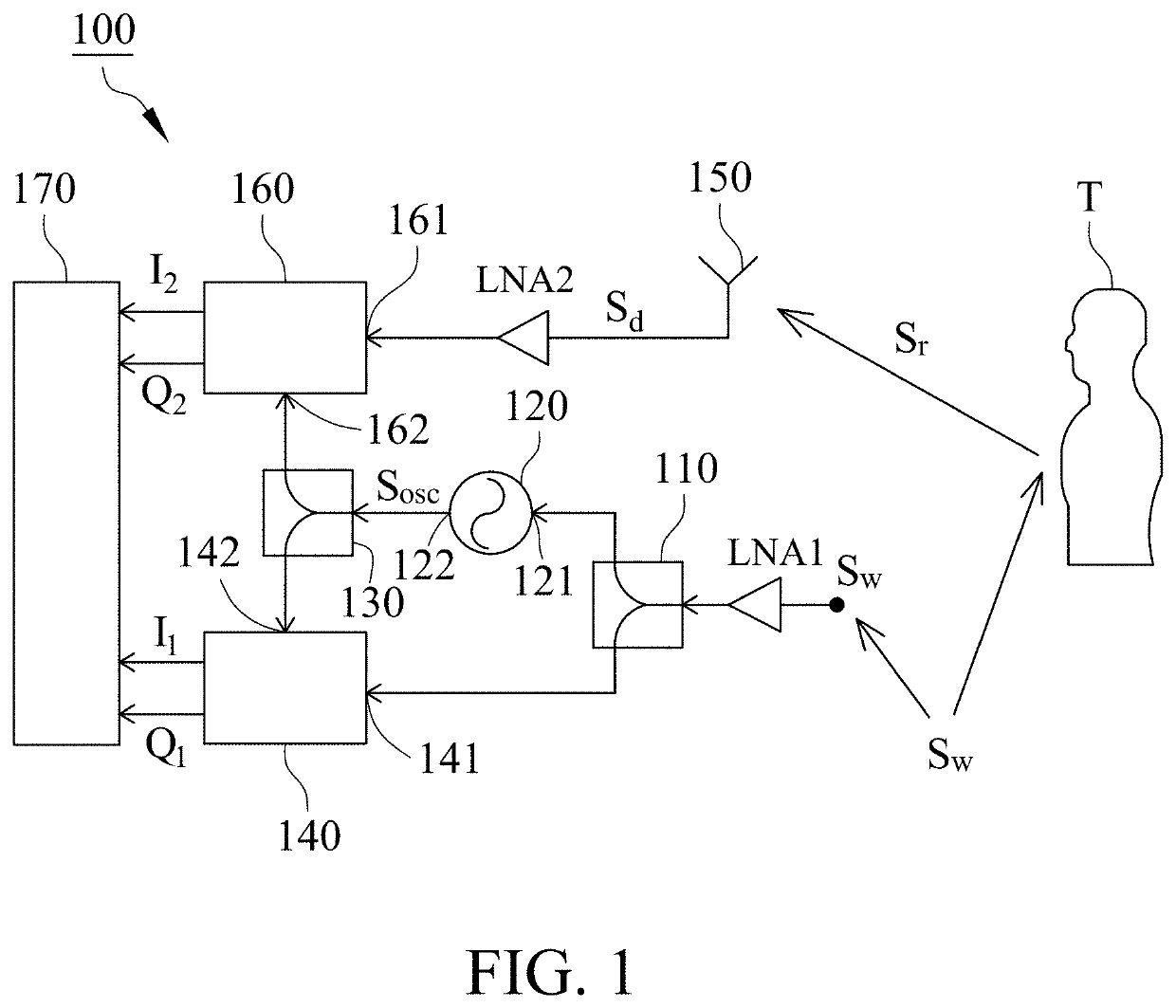
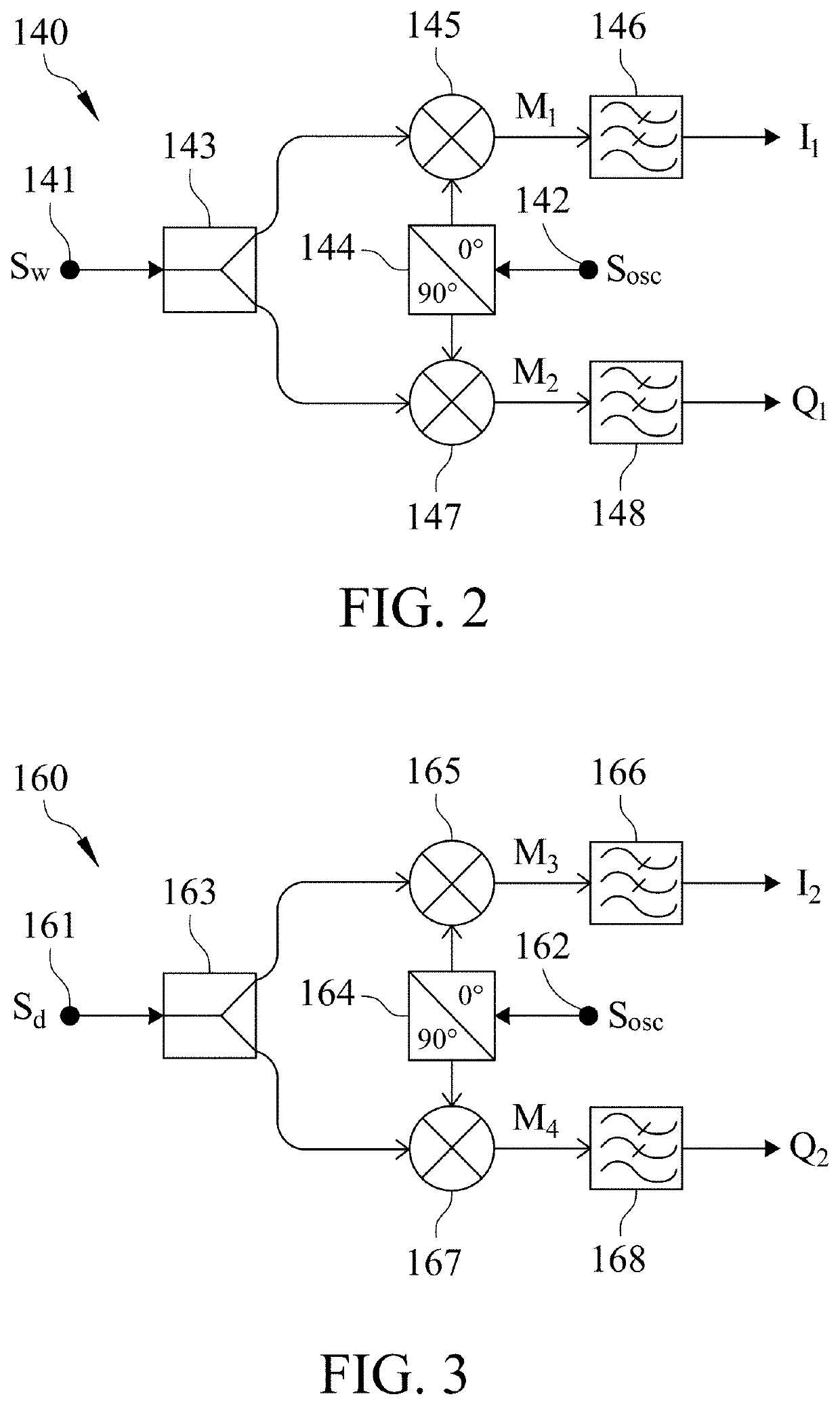
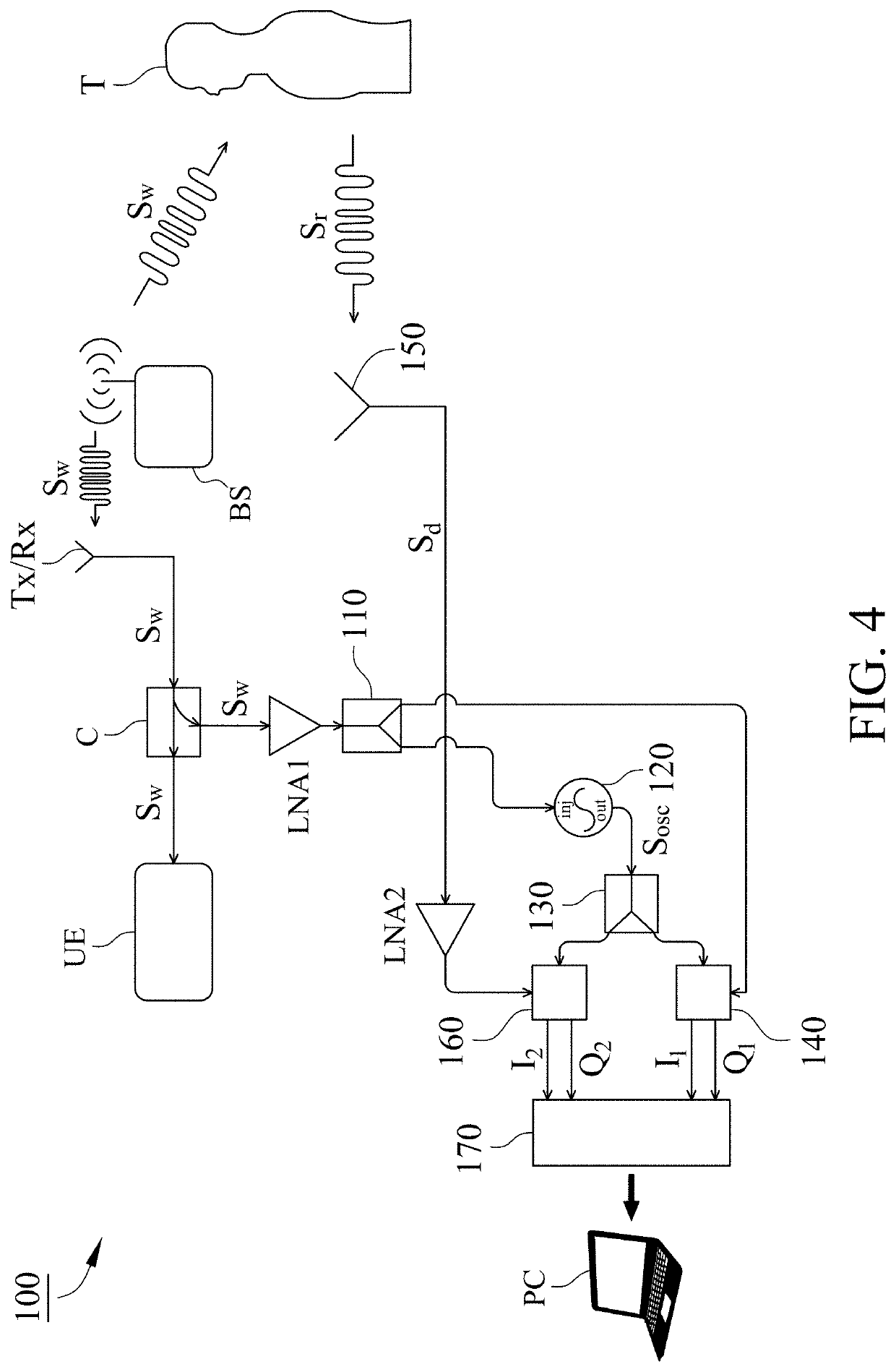
[0015]FIG. 1 is a circuit diagram of a vital-sign radar sensor 100 using wireless internet signals in accordance with one embodiment of the present invention. It includes a first splitter 110, an injection-locked oscillator (ILO) 120, a second splitter 130, a first demodulation unit 140, a receive antenna 150, a second demodulation unit 160 and a processing unit 170.
[0016]The first splitter 110 receives a wireless internet signal SW from a first low-noise amplifier LNA1 and splits it into two parts. The wireless internet signal SW may be an uplink signal or a downlink signal from a wireless internet device that is received by the first splitter 110 via wire or wireless transmission. The wireless internet signal SW is also transmitted to a target T wirelessly, and a reflected signal Sr from the target T is produced accordingly. The reflected signal Sr includes a Doppler shift caused by vital signs of the target T and a modulation component of the wireless internet signal SW.
[0017]The...
PUM
 Abstract
Description
Claims
Application Information
 - R&D Engineer
- R&D Manager
- IP Professional
- Industry Leading Data Capabilities
- Powerful AI technology
- Patent DNA Extraction
Browse by: Latest US Patents, China's latest patents, Technical Efficacy Thesaurus, Application Domain, Technology Topic, Popular Technical Reports.
© 2024 PatSnap. All rights reserved.Legal|Privacy policy|Modern Slavery Act Transparency Statement|Sitemap|About US| Contact US: help@patsnap.com


