Anti-roll bar clamp, Anti-roll bar/Anti-roll bar clamp assembly, and method for producing an Anti-roll bar clamp

a technology of anti-roll bar clamps and clamp assemblies, which is applied in the direction of mechanical equipment, transportation and packaging, and twisting springs, etc., and can solve problems such as loss and loss

Pending Publication Date: 2022-06-23
THYSSENKRUPP FEDERN & STABILISATOREN +1
View PDF32 Cites 0 Cited by
  • Summary
  • Abstract
  • Description
  • Claims
  • Application Information

AI Technical Summary

Benefits of technology

[0031]Within the scope of the present invention, what is to be understood by one-piece is that no piece can be divided into a plurality of pieces in a destruction-free manner.
[0032]In a preferred embodiment of the invention, the stabilizer clamp is formed in one piece, in particular stamped from one piece, or is formed in multiple pieces, in particular in two pieces or three pieces. For example, the stamped stabilizer clamp is substantially produced as a stamped and bent part.
[0033]Within the scope of the present invention, what is to be understood by one-piece is a piece which can be divided into a plurality of pieces only through destruction of material.
[0034]According to a preferred embodiment of the invention, at least one of the at least two at least partially opposite end regions has at least one attachment element for attaching to a vehicle, in particular to a vehicle chassis, a vehicle running-gear unit, a vehicle frame, a vehicle underfloor or combination thereof. An attachment element for example takes the form of at least a form-fitting connecting receptacle,

Problems solved by technology

Furthermore, the mounting operation, in particular the closing of the stabilizer clamp, requires no additional components, in particular connecting elements, which would have to be additionally arranged on the stabilizer clamp, only with effort, and could, for example, become lost.

Method used


Image

  • Anti-roll bar clamp, Anti-roll bar/Anti-roll bar clamp assembly, and method for producing an Anti-roll bar clamp
  • Anti-roll bar clamp, Anti-roll bar/Anti-roll bar clamp assembly, and method for producing an Anti-roll bar clamp
  • Anti-roll bar clamp, Anti-roll bar/Anti-roll bar clamp assembly, and method for producing an Anti-roll bar clamp

Examples


Embodiment Construction

[0025]By way of example, the geometric base area of a rivet and associated rivet hole is selected from a group consisting of a polygon, in particular a trigon, a tetragon, a pentagon, a hexagon, a heptagon, an octagon, a nonagon, a decagon, a hendecagon, a dodecagon, an ellipse, in particular a circle or a combination thereof. For example, the rivet can take the form of a hollow body, in particular of a hollow cylinder, or be solid in form.

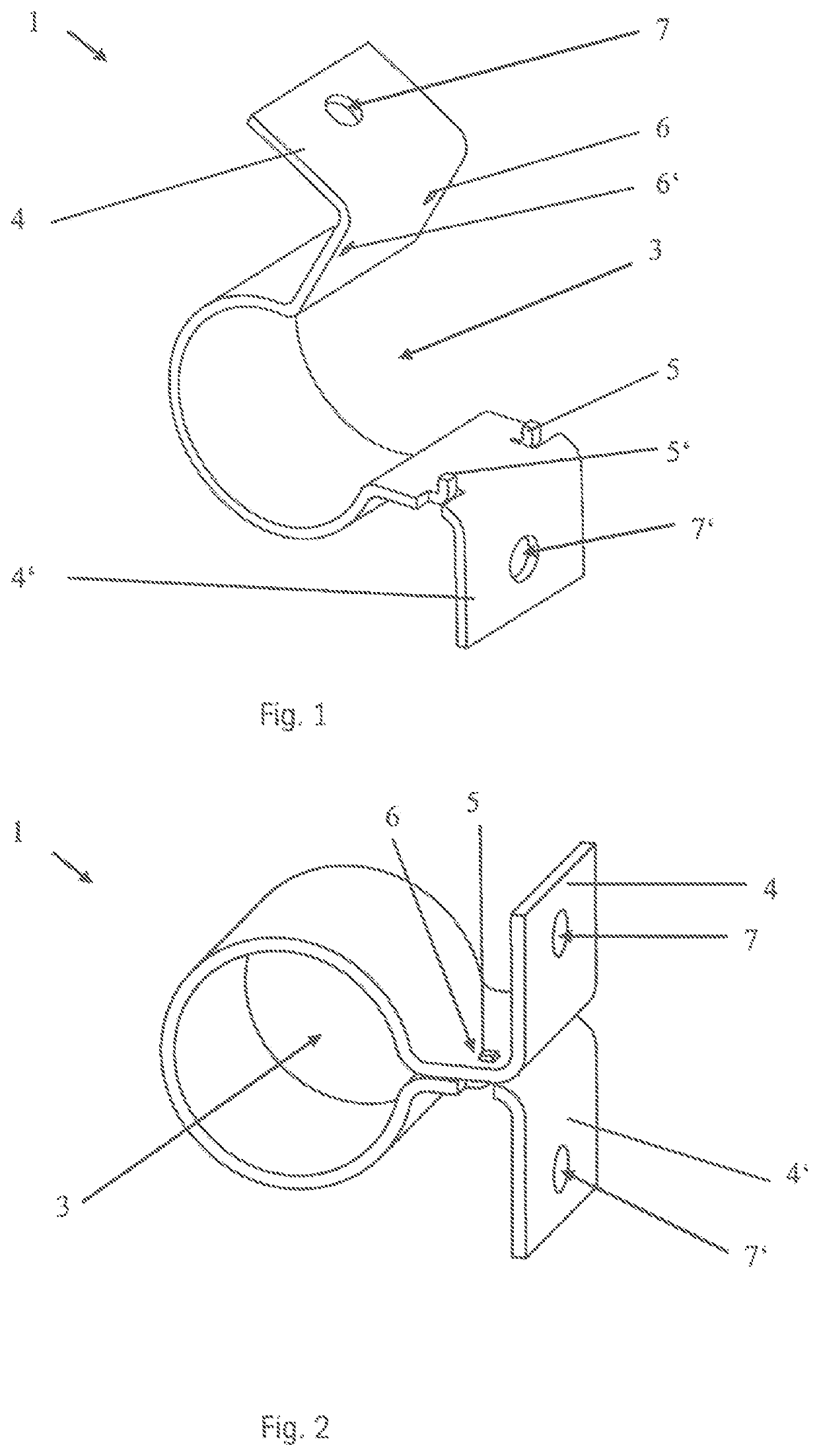
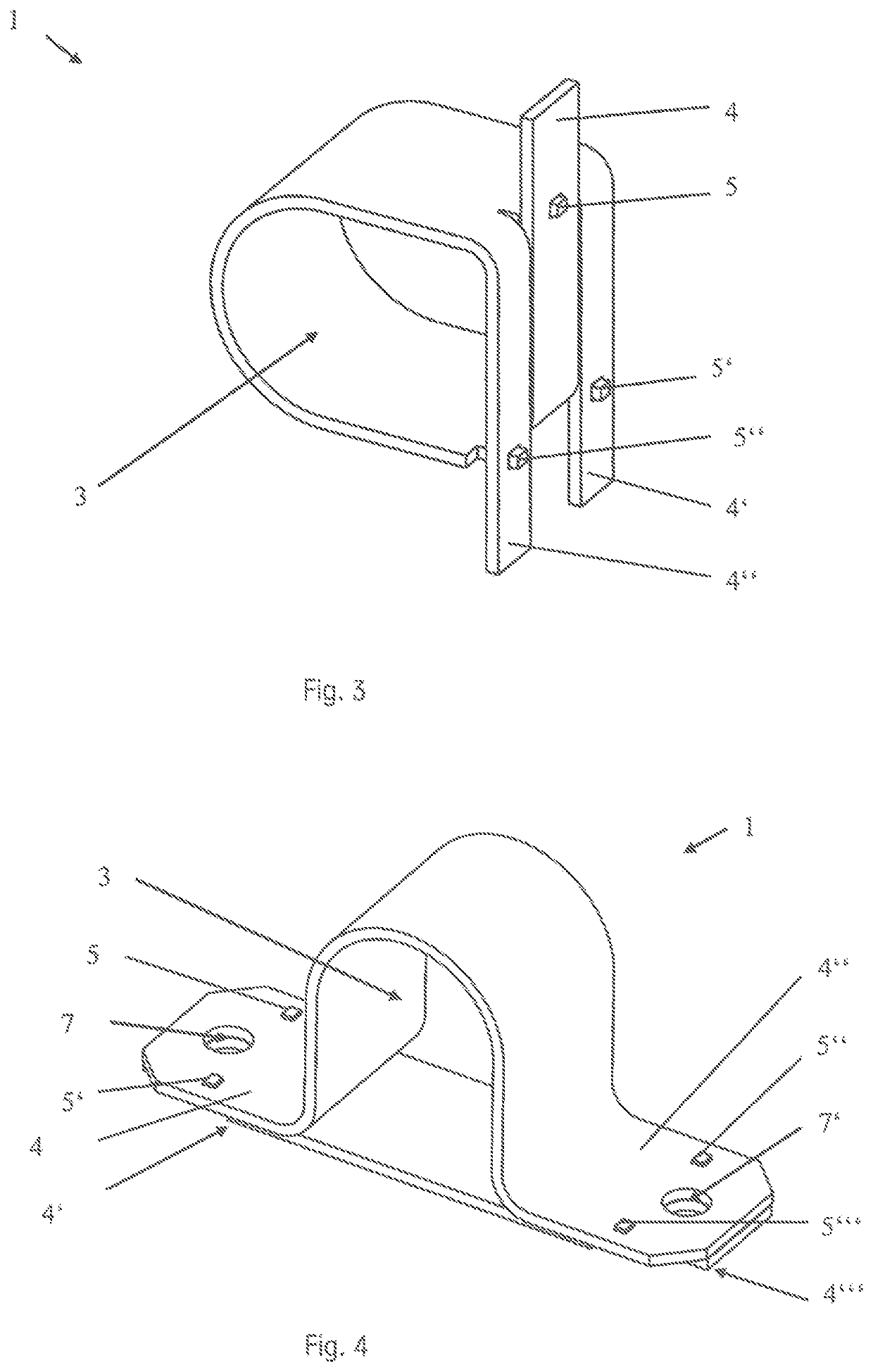
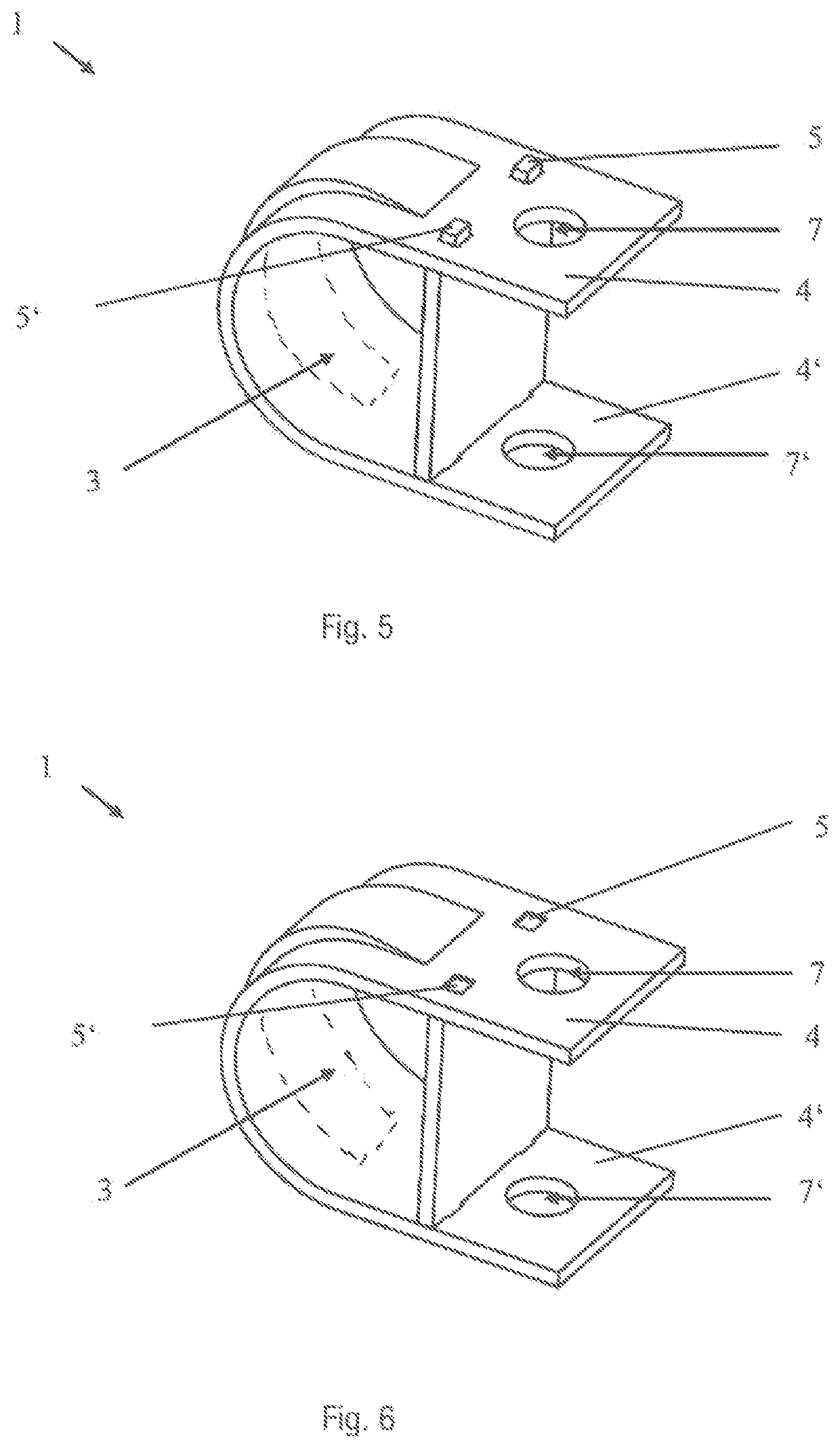
[0026]According to a preferred embodiment of the invention, the stabilizer clamp has at least two rivets and at least two rivet holes, wherein the at least two rivets and the at least two rivet holes each have a like-sided or alternate-sided arrangement.

[0027]Within the scope of the present invention, what is to be understood by a like-sided arrangement is an arrangement in which the at least two rivets or the at least two rivet holes are arranged on the same of the mutually opposite end regions.

[0028]What is to be understood by alternate-sided ar...


PUM


Abstract

A stabilizer clamp for a vehicle stabilizer may include an inner region for receiving a vehicle stabilizer and at least two at least partially opposite end regions for closing the stabilizer clamp. A first of the at least two at least partially opposite end regions may have a connecting element, and a second of the at least two at least partially opposite end regions may have a connecting element receptacle for producing at least a form-fitting connection between the connecting element and the connecting element receptacle. The connecting element may be at least one rivet, and the at least one connecting element receptacle is at least one rivet hole, and the form-fitting connection that is produced is at least a riveted connection.

Description

[0001]The present invention relates to a stabilizer clamp, to a stabilizer / stabilizer clamp assembly and also to a method for producing a stabilizer clamp.PRIOR ART[0002](Vehicle) stabilizers for (motor) vehicles are known from the prior art in a large number of embodiments and are also referred to, for example, as stabilizers, stabilizing torsion bars or torsion spring bars. These stabilizing torsion bars serve for stabilizing against tilting and distortion of the vehicle body, in particular during cornering and tuning of the driving behavior of a (motor) vehicle. Such stabilizers are routinely arranged in the region of the front and the rear axle and usually extend over the entire width of the vehicle. The fastening of such stabilizers to the running-gear unit on the one hand and to the vehicle body on the other hand is associated with the problem that the vibrations, oscillations and noises, such as, for example, wheel noises and roadway noises, which arise and appear at the runn...

Claims


Application Information

Patent Timeline
IPC IPC(8): B60G21/055
CPCB60G21/0551B60G2206/8206B60G2204/1222B60G2202/135B60G2204/43B60G2206/427F16F1/16B60G2204/4307F16F1/3849
Inventor BESTING, PATRICKBERNARD, SEBASTIAN
Owner THYSSENKRUPP FEDERN & STABILISATOREN
Why Eureka
Try Eureka