Polar cap-reinforced pressure vessel

a pressure vessel and polar cap technology, applied in the direction of vessel construction details, vessel geometry/arrangement/size, mechanical equipment, etc., can solve the problems of excessive high transport cost, overbraiding process, and limited variation possibilities in regard to fiber angle, etc., and achieve high torque

Active Publication Date: 2021-10-21
NPROXX BV
View PDF0 Cites 2 Cited by
  • Summary
  • Abstract
  • Description
  • Claims
  • Application Information

AI Technical Summary

Benefits of technology

[0029]In a further embodiment, the outer contour of the pole cap reinforcement layer can be designed in such a way, as to have the cylindrical area of the central part of the pressure vessel initially continued therein in a marginal area of the pole cap as an extended area, and in this way to allow for facilitated deposition, drawn into the pole cap area, of the inner plies of the pressure vessel reinforcement layer in the fo

Problems solved by technology

Light pressure vessels are desired for the transport of the pressure vessels, because a transport of pressure vessels with high vessel weights consumes an unnecessarily large amount of energy and therefore causes excessively high transport costs.
In the overbraiding process, the variation possibilities with regard to the fiber angle are much more limited, because the number of braiding bobbins and the thickness of the fiber used result in a certain fiber angle, which can only be varied within small limits.
The disadvantages of the overbraiding process are fiber corrugation and different laminate quality depending on fiber deposition direction, in particular the difference, whether the braiding occurs from a small diameter to a large diameter or vice versa.
This can lead to a deviation of the fiber bundles caused by the warp threads, which leads to a decrease in the fiber-parallel strength of the tissue.
Theoretically, all winders can be impleme

Method used


Image

  • Polar cap-reinforced pressure vessel
  • Polar cap-reinforced pressure vessel
  • Polar cap-reinforced pressure vessel

Examples


Embodiment Construction

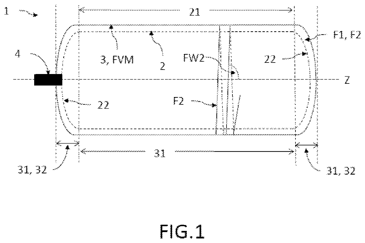
[0039]FIG. 1 shows an embodiment of a pressure vessel 1 according to the invention in the lateral section. This pressure vessel 1 comprises an inner vessel 2 of a cylinder-shaped central part 21 and two dome-shaped pole caps 22 respectively closing the central part 21 on both sides and an outer layer 3 wound on the inner vessel 2 for the reinforcement of the inner vessel 2 against a pressure load, wherein the outer layer 3 comprises at least one pole cap reinforcement layer 31 and a pressure vessel reinforcement layer 32 of fiber composite material (FVM for short), wherein the pole cap reinforcement layer 31 at least partially covers the pole caps 22 and the pressure vessel reinforcement layer 32 covers the pole caps 22 and the central part 21. The fiber angle FW2 is thereby an angle of close to 90° to the cylinder axis Z of the central part, preferably FW2 amounts to more than 80°

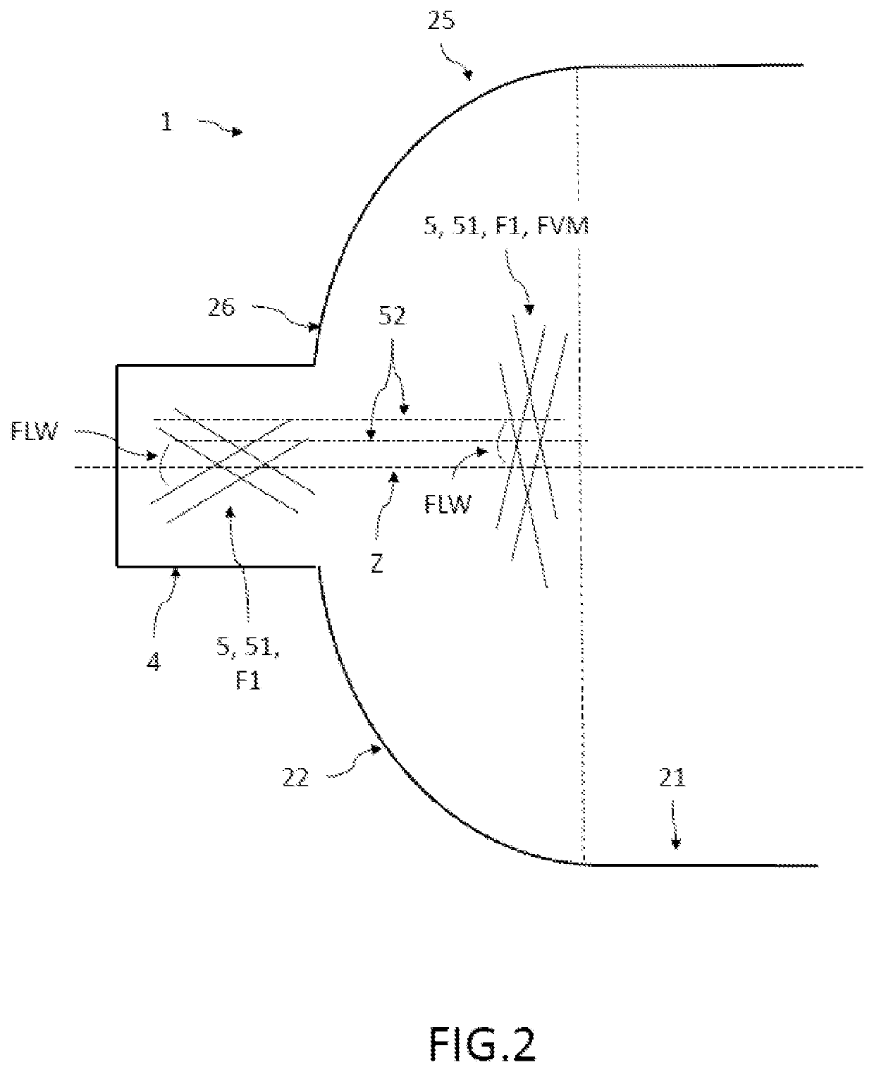
[0040]FIG. 2 shows an embodiment of a pressure vessel 1 according to the invention in the region of the...


PUM

PropertyMeasurementUnit
Angleaaaaaaaaaa
Pressureaaaaaaaaaa
Areaaaaaaaaaaa

Abstract

The invention relates to a pressure vessel with reinforced pole caps and a method for producing such a pressure vessel, which comprises an inner vessel of a cylinder-shaped central part and two dome-shaped pole caps closing the central part on both sides and an outer layer wound on the inner vessel for the reinforcement of the inner vessel against a pressure load, wherein the outer layer comprises at least one pole cap reinforcement layer and a pressure vessel reinforcement layer of fiber composite material, wherein the pole cap reinforcement layer at least partially covers the pole caps and the pressure vessel reinforcement layer covers the pole caps and the central part and a contour-stable preform is arranged as the pole cap reinforcement layer on at least one of the pole caps, preferably on both pole caps.

Description

FIELD OF THE INVENTION[0001]The invention relates to a pressure vessel with reinforced pole caps and to a method for producing such a pressure vessel.BACKGROUND OF THE INVENTION[0002]The market for fiber-reinforced pressure vessels of fiber composite material grows continuously. The increasing extraction of natural gas and tracking gas requires a storage in pressure vessels, especially in countries without a corresponding pipeline network. In addition, there is the automobile sector, which is highly involved in the development of fuel cell vehicles, in which the fuel is to be stored in the form of gaseous hydrogen under high pressure in pressure vessels. Light pressure vessels are desired for the transport of the pressure vessels, because a transport of pressure vessels with high vessel weights consumes an unnecessarily large amount of energy and therefore causes excessively high transport costs.[0003]Currently used pressure vessels have a cylindrical central part, on which pole cap...

Claims


Application Information

Patent Timeline
IPC IPC(8): F17C1/06
CPCF17C1/06F17C2201/0109F17C2203/0604F17C2203/0619F17C2203/0663F17C2270/0168F17C2221/012F17C2221/033F17C2223/0123F17C2223/035F17C2209/234F17C2201/054F17C2201/056F17C2223/036F17C2270/01F17C2203/0609Y02E60/32
Inventor BÄUMER, THOMASMIDDENDORF, CHRISTIAN
Owner NPROXX BV
Why Eureka
Try Eureka