Gas turbine engines having cryogenic fuel systems

a technology of cryogenic fuel and gas turbine engine, which is applied in the direction of turbine/propulsion fuel heating, fuel systems for specific fuels, machines/engines, etc., can solve the problems of varied implementation challenges

Active Publication Date: 2022-06-23
RTX CORP
View PDF6 Cites 6 Cited by
  • Summary
  • Abstract
  • Description
  • Claims
  • Application Information

AI Technical Summary

Benefits of technology

[0019]In addition to one or more of the features described above, or as an alternative, embodiments of the aircraft engine systems may include that the fuel is one of liquid hydrogen and liquid methane.
[0020]In addition to one or more of the features described above, or as an alternative, embodiments of the aircraft engine systems may include that the expansion turbine is configured to impart work to the drive shaft during expansion of the fuel.
[0021]In addition to one or more of the features described above, or as an alternative, embodiments of the aircraft engine systems may include a flow supply line fluidly connecting the cryogenic fuel tank to the combustor with the expansion turbine arranged between the cryogenic fuel tank and the combustor along the flow supply line.
[0022]In addition to one or more of the features described above, or as an alternative, embodiments of the aircraft engine systems may include that the combustor, the drive shaft, the compressor section, and the turbine section are arranged as a turboshaft engine or a turboprop engine.
[0023]In addition to one or more of the features described above, or as an alternative, embodiments of the aircraft engine systems may include that the combustor, the drive shaft, the compressor section, and the turbine section are arranged as a turbofan engine.
[0024]The foregoing features and elements may be executed or utilized in various combinations without exclusivity, unless expressly indicated otherwise. These features and elements as well as the operation thereof will become more apparent in light of the following description and the accompanying drawings. It should be understood, however, that the following description and drawings are intended to be illustrative and explanatory in nature and non-limiting.

Problems solved by technology

Alternative fuels have been considered, but suffer from various challenges for implementation, particularly on aircraft.

Method used


Image

  • Gas turbine engines having cryogenic fuel systems
  • Gas turbine engines having cryogenic fuel systems
  • Gas turbine engines having cryogenic fuel systems

Examples


Embodiment Construction

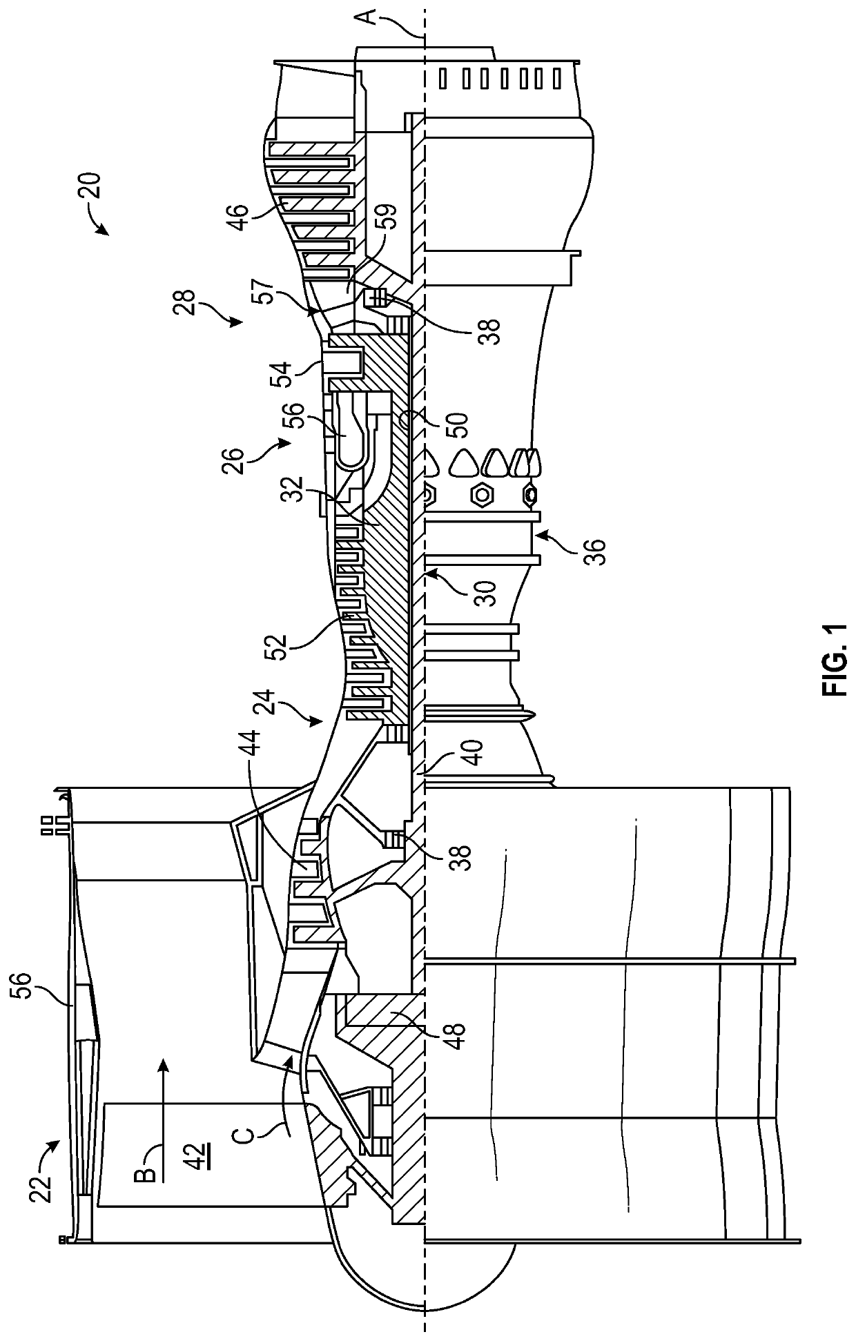
[0030]FIG. 1 schematically illustrates a gas turbine engine 20. As illustratively shown, the gas turbine engine 20 is configured as a two-spool turbofan that has a fan section 22, a compressor section 24, a combustor section 26, and a turbine section 28. The illustrative gas turbine engine 20 is merely for example and discussion purposes, and those of skill in the art will appreciate that alternative configurations of gas turbine engines may employ embodiments of the present disclosure. The fan section 22 includes a fan 42 that is configured to drive air along a bypass flow path B in a bypass duct defined in a fan case 15. The fan 42 is also configured to drive air along a core flow path C for compression and communication into the combustor section 26 then expansion through the turbine section 28. Although depicted as a two-spool turbofan gas turbine engine in the disclosed non-limiting embodiment, it should be understood that the concepts described herein are not limited to use wi...


PUM


Abstract

Turbine engine systems and aircraft having such systems are described. The turbine engine systems include a combustor arranged along a core flow path of the turbine engine, a drive shaft having at least a compressor section and a turbine section coupled thereto, a cryogenic fuel tank configured to supply a fuel to the combustor, and an expansion turbine mechanically coupled to the drive shaft, the expansion turbine configured to receive fuel from the cryogenic fuel tank and expand said fuel, wherein expansion of said fuel by the expansion turbine drives rotation of the expansion turbine to provide power input to the drive shaft.

Description

TECHNICAL FIELD[0001]The present disclosure relates generally to gas turbine engines, and more specifically to employing cryogenic fuel systems and related systems with gas turbine engines.BACKGROUND[0002]Gas turbine engines, such as those utilized in commercial and military aircraft, include a compressor section that compresses air, a combustor section in which the compressed air is mixed with a fuel and ignited, and a turbine section across which the resultant combustion products are expanded. The expansion of the combustion products drives the turbine section to rotate. As the turbine section is connected to the compressor section via a shaft, the rotation of the turbine section drives the compressor section to rotate. In some configurations, a fan is also connected to the shaft and is driven to rotate via rotation of the turbine.[0003]Typically, liquid fuel is employed for combustion onboard an aircraft, in the gas turbine engine. The liquid fuel has conventionally been a hydroc...

Claims


Application Information

Patent Timeline
Patent Type & Authority Applications(United States)
IPC IPC(8): F02C7/224F02C7/16F02C7/141F02C3/22F02C7/06B64D37/30B64D37/34
CPCF02C7/224F02C7/16F02C7/141F02C3/22F02C7/06F05D2260/98B64D37/34F05D2220/323F05D2260/213F05D2260/232B64D37/30F02K3/06F02C6/206F02C3/107
Inventor JOHNSON, STEVEN B.MURPHY, ANDREW J.
Owner RTX CORP
Why Eureka
Try Eureka