Supercharge Your Innovation With Domain-Expert AI Agents!

Electroluminescence display apparatus

a technology of display apparatus and electroluminescence, which is applied in the direction of electrical apparatus, semiconductor devices, instruments, etc., can solve the problems of low compensation performance, limitation of image implementation, and deviation of luminance, and achieve the effect of increasing sensing performan

Pending Publication Date: 2022-06-23
LG DISPLAY CO LTD
View PDF0 Cites 0 Cited by
  • Summary
  • Abstract
  • Description
  • Claims
  • Application Information

AI Technical Summary

Benefits of technology

The present invention is about an electroluminescence display that can improve its sensing performance. This means that the display can detect and respond to touch or pressure more easily and accurately. This is useful for improving the user experience and enhancing the functionality of the display.

Problems solved by technology

Such a driving characteristic difference causes a luminance deviation, and due to this, there is a limitation in implementing an image.
Compensation technology for compensating for a luminance deviation between pixels has been proposed, but is not high in compensation performance because sensing performance is low.

Method used


Image

  • Electroluminescence display apparatus
  • Electroluminescence display apparatus
  • Electroluminescence display apparatus

Examples


first embodiment

[0066]FIG. 5 is a diagram illustrating an example of a sensing circuit connected to one pixel of a display panel

[0067]Referring to FIG. 5, in performing the display driving operation, the sensing circuit 22 may supply the pixel reference voltage PVREF to a pixel PXL through the reference voltage line 150, and in performing the sensing driving operation succeeding the display driving operation, the sensing circuit 22 may sense a pixel current IPIX, flowing in the pixel PXL, through the reference voltage line 150.

[0068]The sensing circuit 22 may include a sensing channel terminal SCH connected to the reference voltage line 150, a switch RPRE connected between the sensing channel terminal SCH and an input terminal for the pixel reference voltage PVREF, a current integrator CI which senses the pixel current IPIX input through the sensing channel terminal SCH, a sampling circuit SH which samples an output CI-OUT of the current integrator CI, a scaler SCR which shifts an output level of t...

second embodiment

[0081]FIG. 8 is a diagram illustrating another example of a sensing circuit 22 connected to one pixel of a display panel. The sensing circuit 22 of FIG. 8 may further include a switch PSAM and a capacitor CSAM, and thus, may minimize an adverse effect of power noise described above.

[0082]Referring to FIG. 8, in performing the display driving operation, the sensing circuit 22 may supply a pixel reference voltage PVREF to a pixel PXL through a reference voltage line 150, and in performing the sensing driving operation succeeding the display driving operation, the sensing circuit 22 may sense a pixel current IPIX, flowing in the pixel PXL, through the reference voltage line 150.

[0083]The sensing circuit 22 may include a sensing channel terminal SCH connected to the reference voltage line 150, a switch RPRE connected between the sensing channel terminal SCH and an input terminal for the pixel reference voltage PVREF, a current integrator CI which senses the pixel current IPIX input thro...


PUM


Abstract

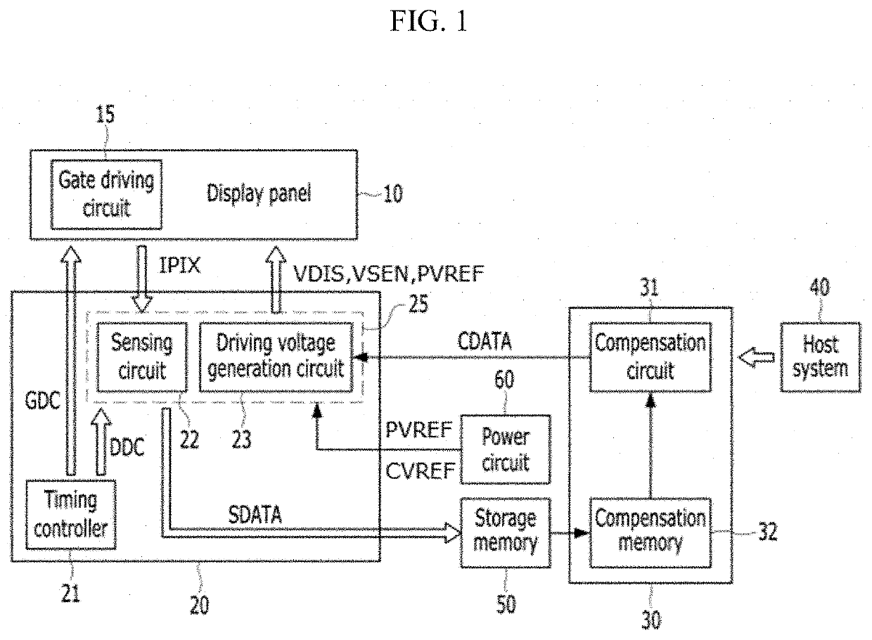
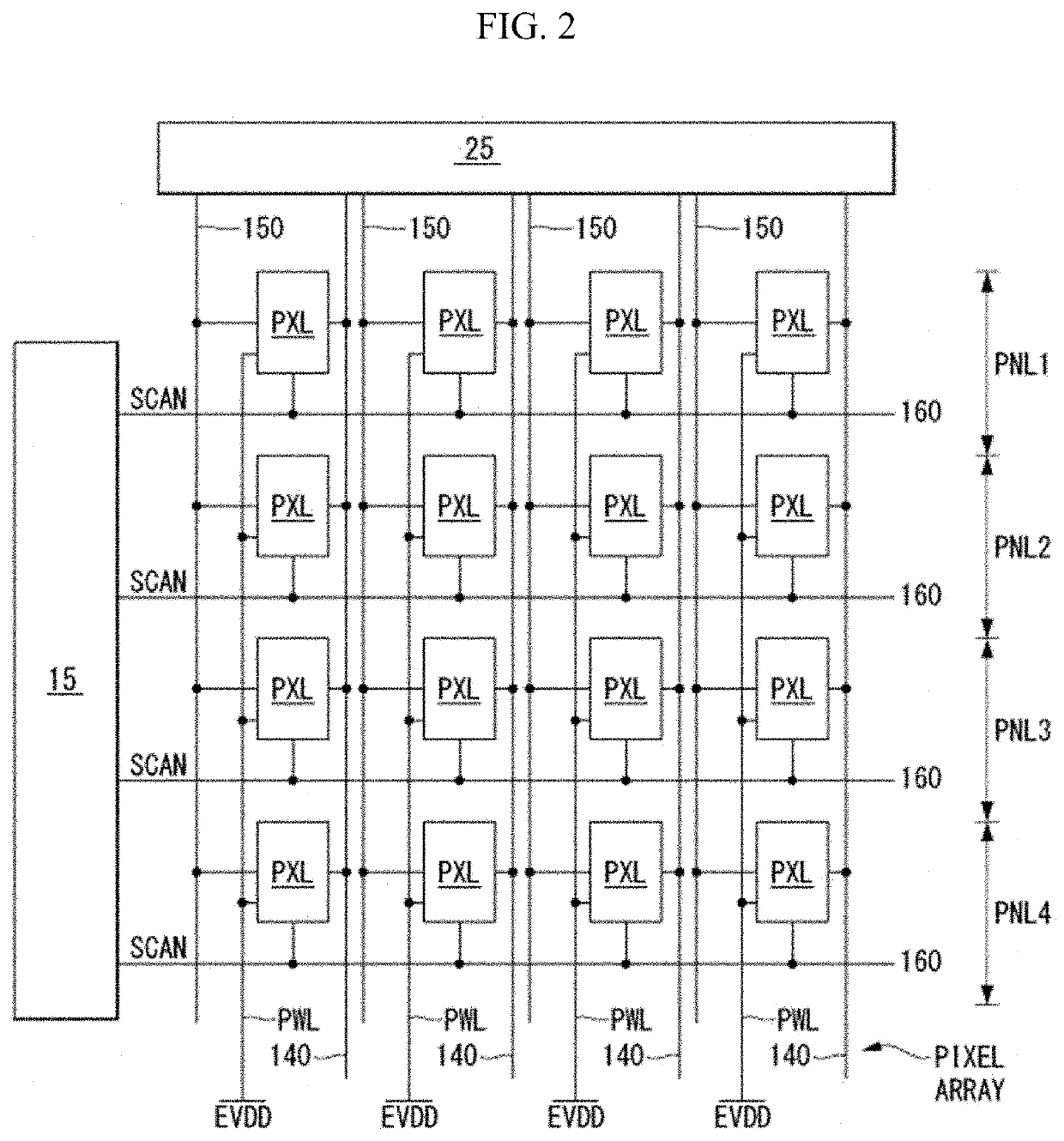
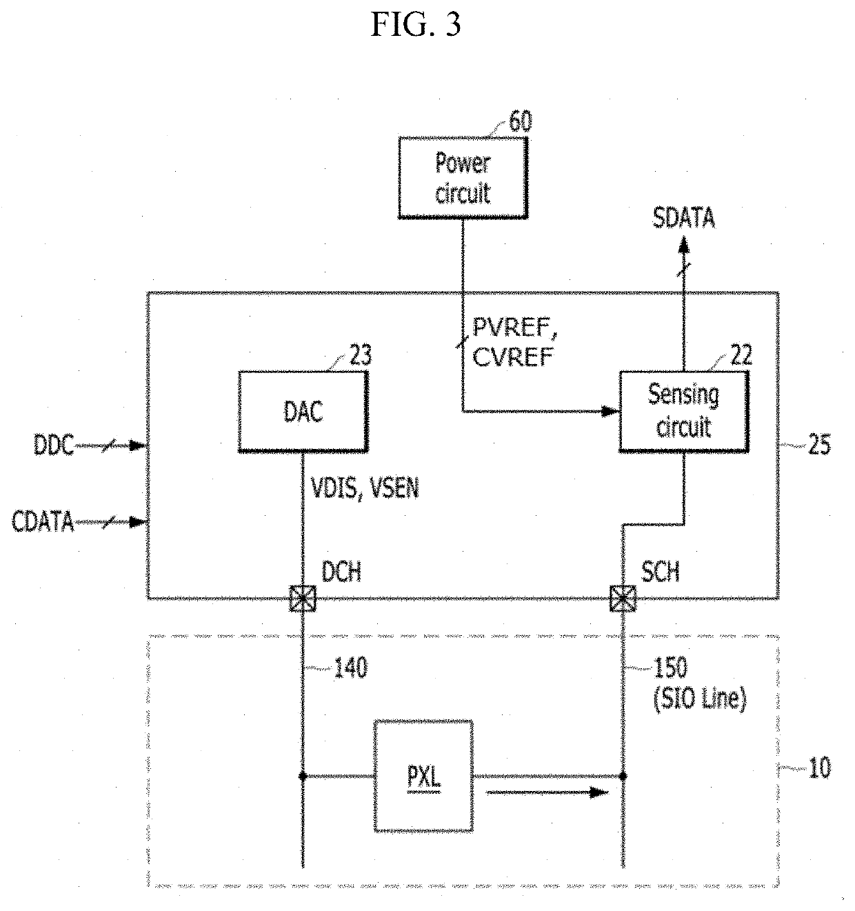
An electroluminescence display apparatus includes a pixel and a sensing circuit supplying a pixel reference voltage to the pixel through a reference voltage line during display driving and sensing a pixel current, flowing in the pixel, through the reference voltage line during sensing driving succeeding the display driving operation. The sensing circuit includes a sensing channel terminal connected to the reference voltage line, a first switch between the sensing channel terminal and an input terminal for the pixel reference voltage, an integrator amplifier including a first input terminal, a second input terminal, and an output terminal, an input terminal for an integrator reference voltage connected to the second input terminal, a second switch between the first input terminal and the output terminal, a first capacitor between the sensing channel terminal and the first input terminal, and a second capacitor between the sensing channel terminal and the output terminal.

Description

CROSS-REFERENCE TO RELATED APPLICATIONS[0001]This application claims the benefit of the Korean Patent Application No. 10-2020-0177267 filed on Dec. 17, 2020, which is hereby incorporated by reference as if fully set forth herein.BACKGROUNDTechnical Field[0002]The present disclosure relates to an electroluminescence display apparatus.Discussion of the Related Art[0003]In electroluminescence display apparatuses having an active matrix type, a plurality of pixels each including a light emitting device and a driving element are arranged as a matrix type, and the luminance of an image implemented by the pixels is adjusted based on a gray level of image data. The driving element controls a pixel current flowing in the light emitting device on the basis of a voltage (hereinafter referred to as a gate-source voltage) applied between a gate electrode and a source electrode thereof. The amount of light emitted by the light emitting device and the luminance of a screen are determined based on ...

Claims


Application Information

Patent Timeline
IPC IPC(8): H01L33/62H01L27/15G09G3/32
CPCH01L33/62H01L27/156G09G2310/0291G09G2310/061G09G3/32G09G3/3225G09G3/3233G09G3/3275G09G2320/0295G09G2320/045G09G3/3258G09G3/325G09G2320/0233
Inventor CHOI, JI SULIM, MYUNG GILEE, BYUNG JAEHEO, JUNG
Owner LG DISPLAY CO LTD
Features
  • R&D
  • Intellectual Property
  • Life Sciences
  • Materials
  • Tech Scout
  • Unparalleled Data Quality
  • Higher Quality Content
  • 60% Fewer Hallucinations
Learn More