Supercharge Your Innovation With Domain-Expert AI Agents!

Piezoelectric vibrator and manufacturing method therefor

a technology of vibrating device and manufacturing method, which is applied in the direction of piezoelectric/electrostrictive/magnetostrictive devices, electrical apparatus, impedence networks, etc., can solve the problem of frequency fluctuations sometimes occurring, and achieve the effect of improving frequency stability

Pending Publication Date: 2022-06-23
MURATA MFG CO LTD
View PDF0 Cites 0 Cited by
  • Summary
  • Abstract
  • Description
  • Claims
  • Application Information

AI Technical Summary

Benefits of technology

The present invention provides a piezoelectric vibrator that has better frequency stability and a method for manufacturing it. This helps improve the reliability and performance of the vibrator.

Problems solved by technology

However, with the method described in Patent Document 1, frequency fluctuations sometimes occurred as a result of the chromium of the base film diffusing during the process of manufacturing the piezoelectric vibrator and rising up from grain boundaries between gold grains and the chromium exposed from the monomolecular film becoming oxidized or hydroxylated.

Method used


Image

  • Piezoelectric vibrator and manufacturing method therefor
  • Piezoelectric vibrator and manufacturing method therefor
  • Piezoelectric vibrator and manufacturing method therefor

Examples


first embodiment

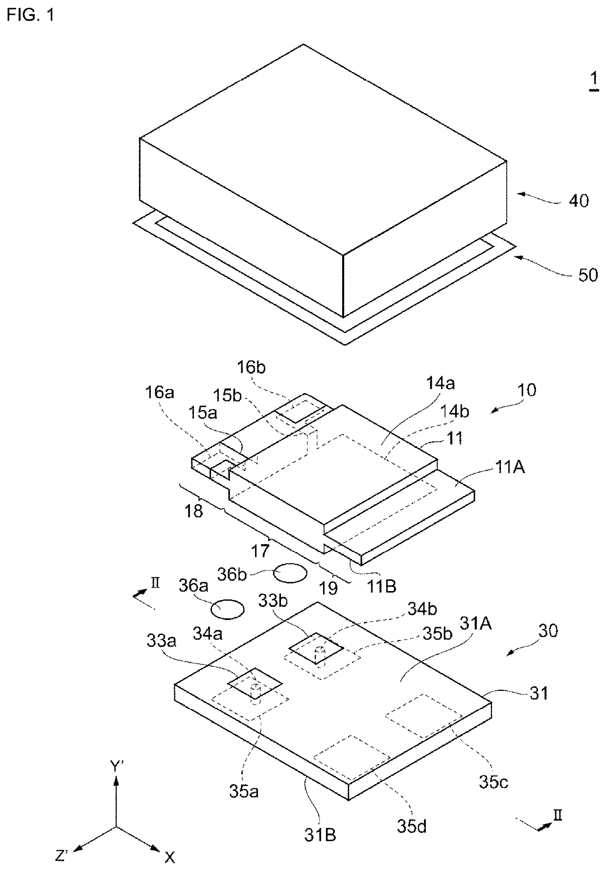
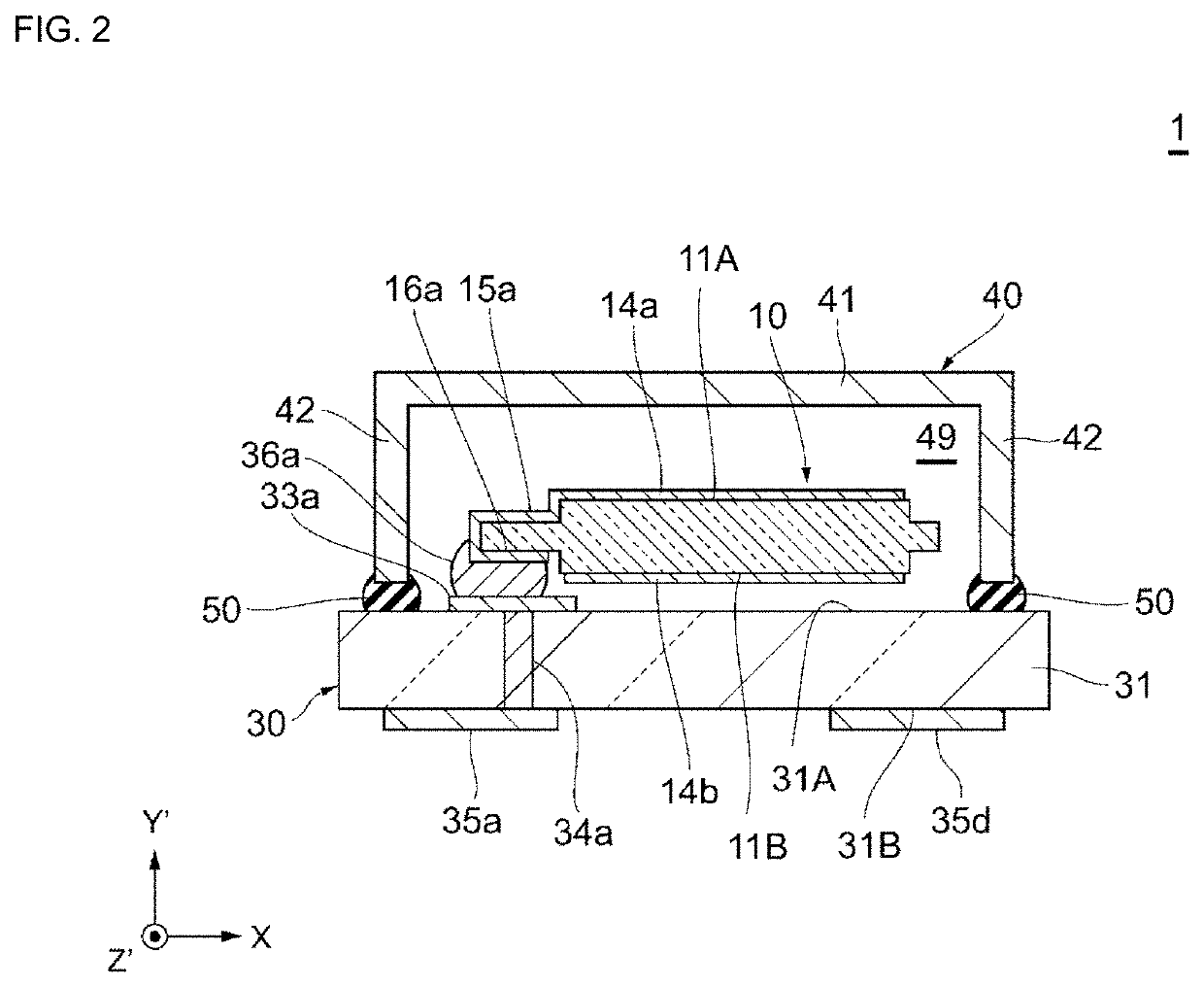
[0023]The configuration of a crystal vibrator 1 according to a First Embodiment of the present invention will be described while referring to FIGS. 1 and 2. FIG. 1 is an exploded perspective view schematically illustrating the configuration of the crystal vibrator according to the First Embodiment. FIG. 2 is a sectional view schematically illustrating the configuration of the crystal vibrator according to the First Embodiment.

[0024]For convenience, each drawing may be labeled with a Cartesian coordinate system consisting of an X axis, a Y′ axis, and a Z′ axis in order to help clarify the relationships between the individual drawings and to aid in understanding the positional relationships between the individual components. The X axis, the Y′ axis, and the Z′ axis correspond to one another in the individual drawings. The X axis, the Y′ axis, and the Z′ axis respectively correspond to the crystallographic axes of a crystal piece 11, which is described later. The X axis corresponds to ...


PUM

PropertyMeasurementUnit
angle ofaaaaaaaaaa
temperatureaaaaaaaaaa

Abstract

A piezoelectric vibrator having a piezoelectric vibration element that includes a piezoelectric piece and a pair of electrodes that face each other with the piezoelectric piece interposed therebetween; a holder that accommodates the piezoelectric vibration element; a resin layer covering at least one electrode of the pair of electrodes; and a water-repellent layer, which has a lower moisture permeability than the resin layer, between the electrode and the resin layer.

Description

CROSS REFERENCE TO RELATED APPLICATIONS[0001]The present application is a continuation of International application No. PCT / JP2020 / 019308, filed May 14, 2020, which claims priority to Japanese Patent Application No. 2019-175977, filed Sep. 26, 2019, the entire contents of each of which are incorporated herein by reference.FIELD OF THE INVENTION[0002]The present invention relates to a piezoelectric vibrator and a manufacturing method therefor.BACKGROUND OF THE INVENTION[0003]Piezoelectric vibrators are used as timing devices, sensors, oscillators, and so on in various electronic appliances such as mobile communication terminals, communication base stations, home appliances, and so forth. For example, a piezoelectric vibrator consists of a piezoelectric vibration element, which includes a mechanical vibration part that converts electrical vibrations into mechanical vibrations using the piezoelectric effect, a holder that accommodates the piezoelectric vibration element, and an electri...

Claims


Application Information

Patent Timeline
Patent Type & Authority Applications(United States)
IPC IPC(8): H01L41/047H03H9/19H03H3/02H10N30/87
CPCH01L41/0475H03H3/02H03H9/19H03H9/1021H03H9/0519H03H3/04H03H2003/0485H10N30/875
Inventor OJIMA, SHIGEOUSHIRO, MASAKI
Owner MURATA MFG CO LTD
Features
  • R&D
  • Intellectual Property
  • Life Sciences
  • Materials
  • Tech Scout
  • Unparalleled Data Quality
  • Higher Quality Content
  • 60% Fewer Hallucinations
Learn More